windshield Wipers
With the use of the extended windshield on my project car, it became evident that there was going to be a serious problem with the wipers......... more specifically, the stock wipers would actually be located inside the windshield. It is necessary for the wipers to be moved forward ahead of the base of the new windshield. This is fine for the driver side wiper as there is still room between the front firewall and the edge of the glass. The passenger side wiper, which is located on the center line of the car is not so lucky as the edge of the new glass actually sweeps forward all the way to the firewall. So my plan is to move the driver side forward to clear the lower edge of the glass and mirror this wiper all the way over to the passenger side. This means that the wipers will now have to sweep toward each other as opposed to the stock arrangement of sweeping in the same direction. In order for this to work, it is necessary to change the direction of sweep of the passenger side wiper.
Oct 18 2013
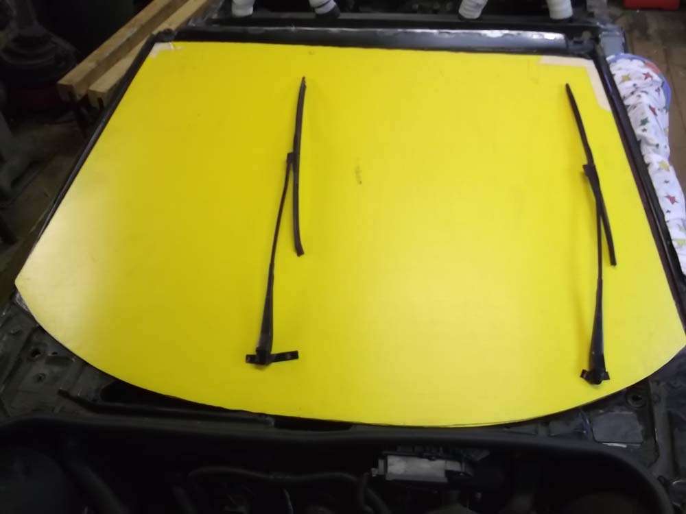
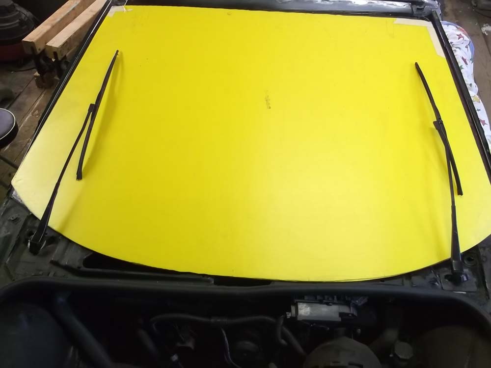
Here is my yellow plastic template of the extended windshield with the wipers shown in the stock position and the future modified position. It's clear to see that having the wipers moved forward and outward to clear the lower edge of the extended glass will mean they have to sweep towards each other.
Here is my yellow plastic template of the extended windshield with the wipers shown in the stock position and the future modified position. It's clear to see that having the wipers moved forward and outward to clear the lower edge of the extended glass will mean they have to sweep towards each other.
This is what the sweep of both wipers will look like. The coverage will be sufficient considering my car will have no roof and likely never see a drop of rain. :)
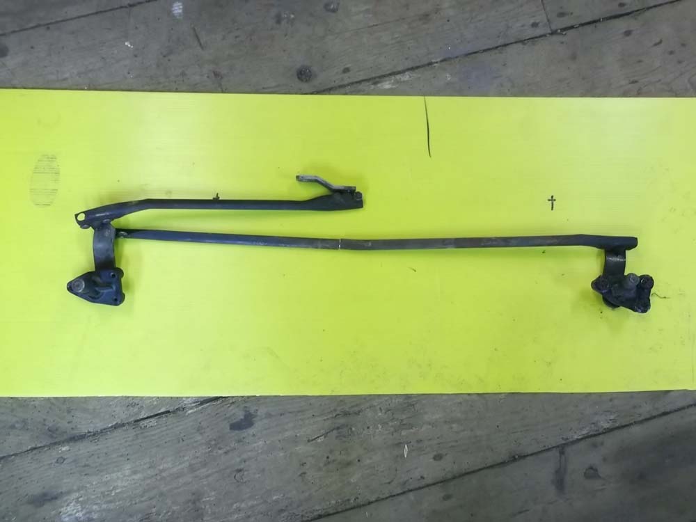
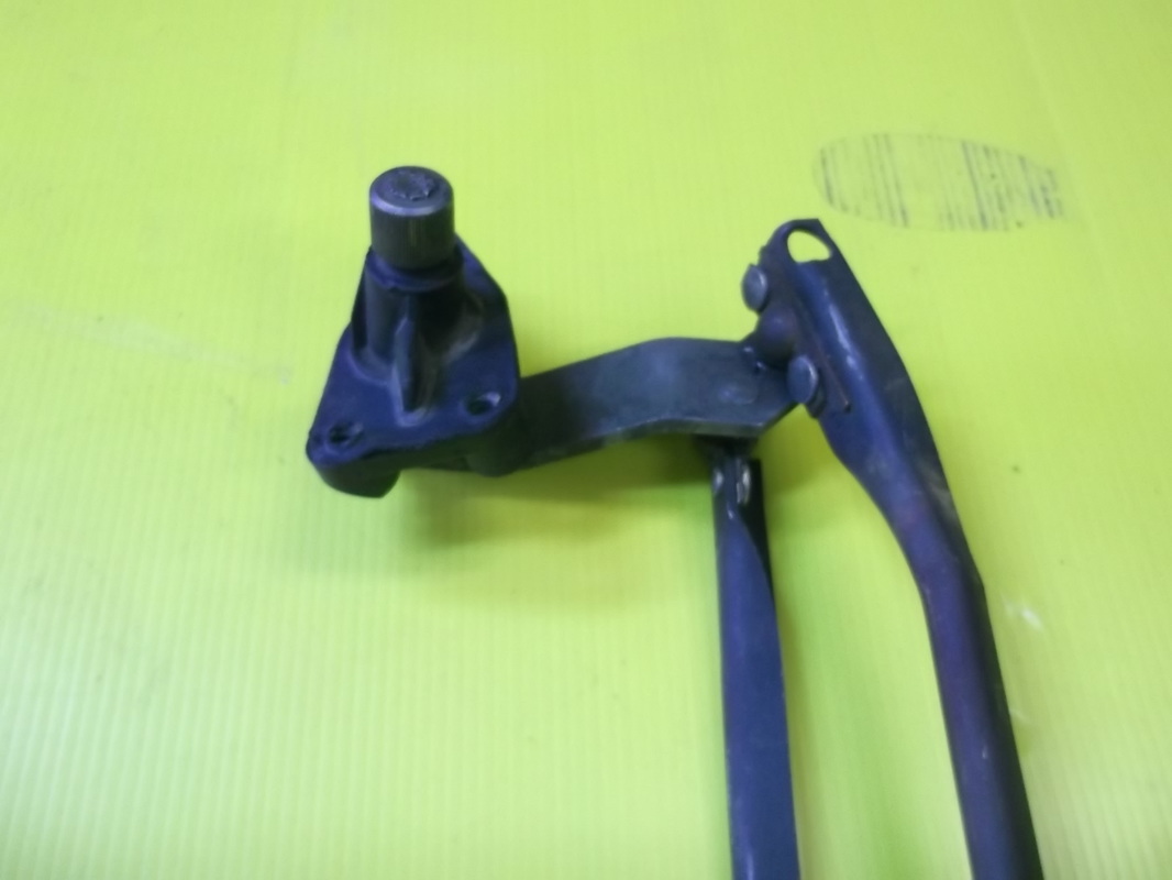
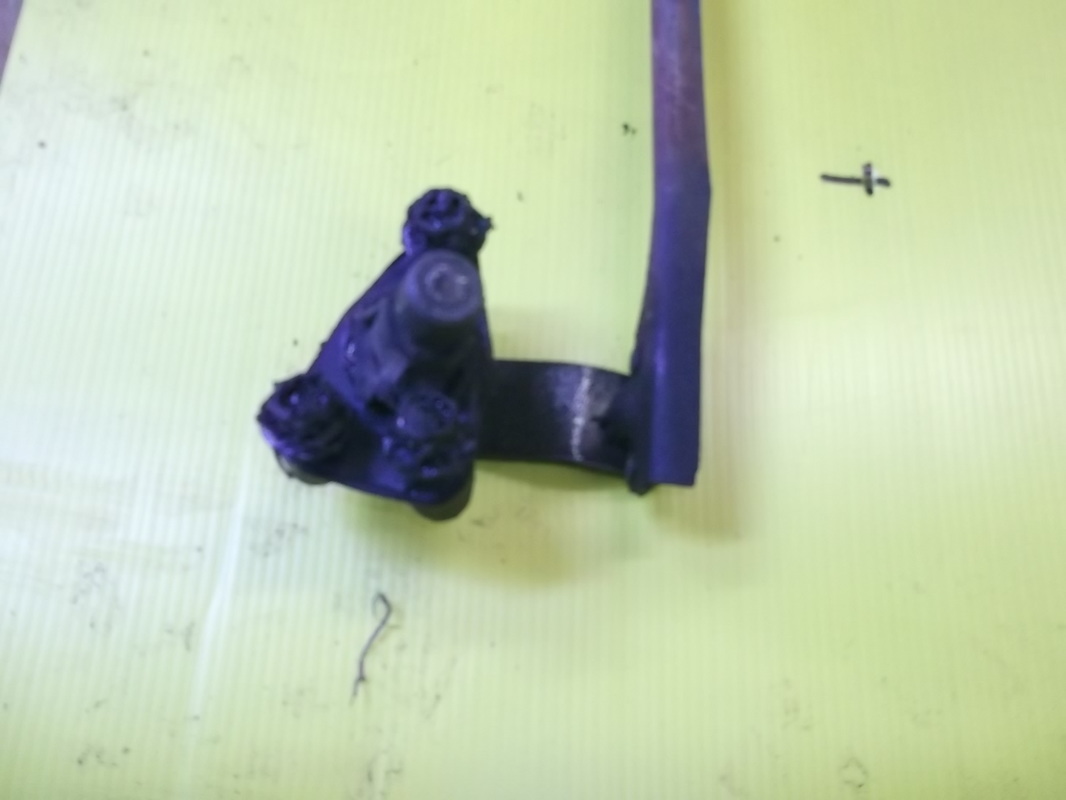
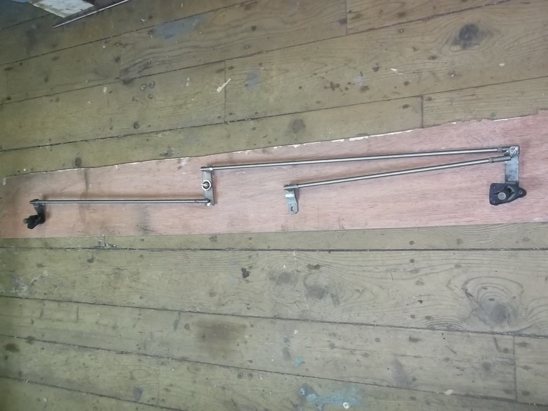
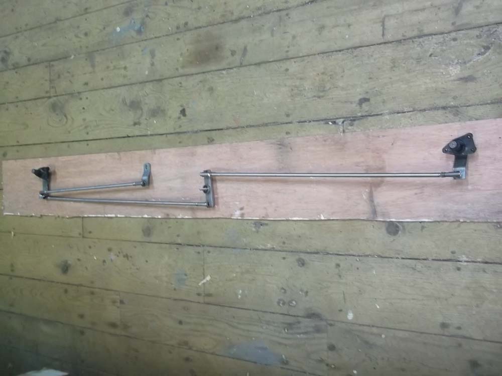
This is the stock wiper linkage removed from the car and assembled with pivots and linkages but without the wiper arms and blades. The short linkage connects the wiper motor to the drivers side pivot point ( driver side wiper). From this pivot, the long linkage connects to the passenger side pivot ( passenger side wiper).
My goal for this little project is to retain the stock location of the wiper motor and then modify the linkages to make the new system function as required. After examining the stock wiper mechanism, I decided to retain the two (2) stock wiper arm pivots as they would be required for the new design. The stock linkages found a new home in the scrap metal bucket.
Nov 9 2013
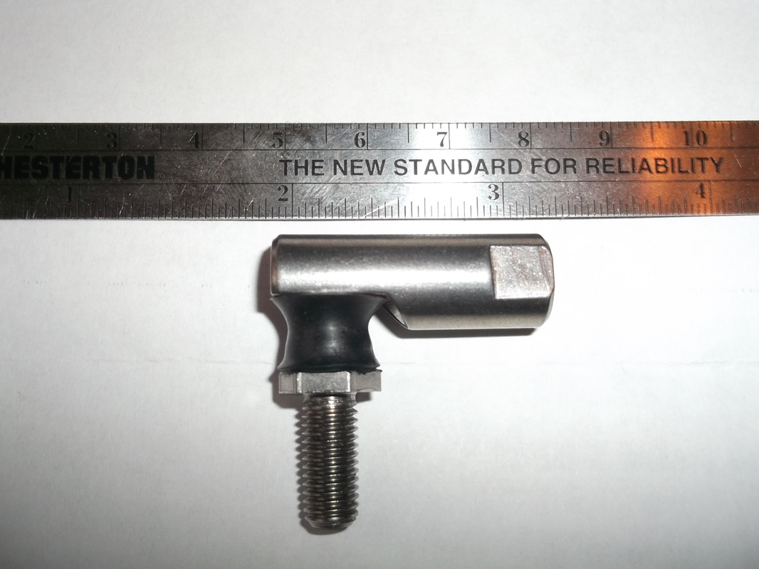
With the stock linkages gone, then so were the stock linkage ball joints that allowed everything to move freely. Looking closely, these ball joints were little more than a press formed copper band held in place over a small ball joint to form a simple ball and socket joint with two rivets. It was clear I was going to have to find an off the shelf replacement that functioned in the same manner. I also decided that the old press formed linkages would be replaced with new linkages made from rods with threaded ends. I pulled out the old material bible ( McMaster Carr catalogue) and searched for a suitable ball joint style connection. Here is what I found. This is a shielded ball joint linkage (M-C Pt No. 6058K36) with a 1/4"-28 female threaded shank and male stud. These units have a 35 deg swivel angle and are all stainless steel construction.
With the stock linkages gone, then so were the stock linkage ball joints that allowed everything to move freely. Looking closely, these ball joints were little more than a press formed copper band held in place over a small ball joint to form a simple ball and socket joint with two rivets. It was clear I was going to have to find an off the shelf replacement that functioned in the same manner. I also decided that the old press formed linkages would be replaced with new linkages made from rods with threaded ends. I pulled out the old material bible ( McMaster Carr catalogue) and searched for a suitable ball joint style connection. Here is what I found. This is a shielded ball joint linkage (M-C Pt No. 6058K36) with a 1/4"-28 female threaded shank and male stud. These units have a 35 deg swivel angle and are all stainless steel construction.
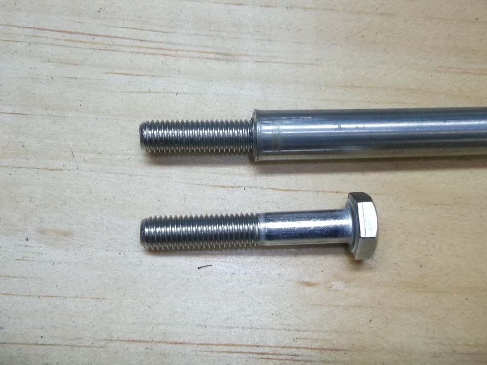
The stock linkages will be replaced with 3/8" x 0.065" stainless steel tubing and to make the threaded ends needed to screw into the ball joint linkage will be made by cutting the heads off 1/4" - 28 stainless steel bolts and then inserting the modify bolt into the linkage tubing. Its a perfect fit and once everything is built and test fit, I will TIG weld them in place. I will add a couple thin 1/4" - 28 jam nuts to the linkage as well to help keep everything tight during final assembly.
Nov 12 2013
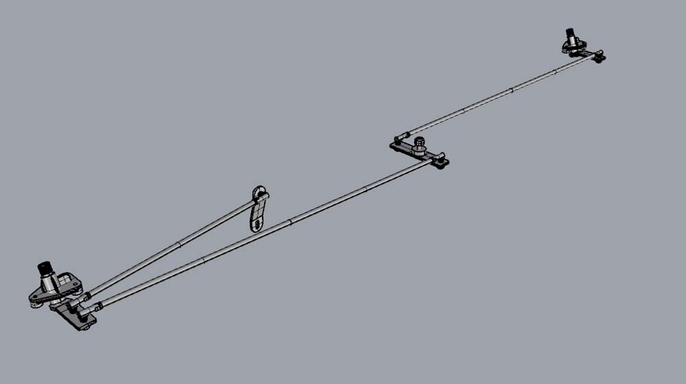
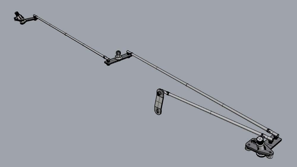
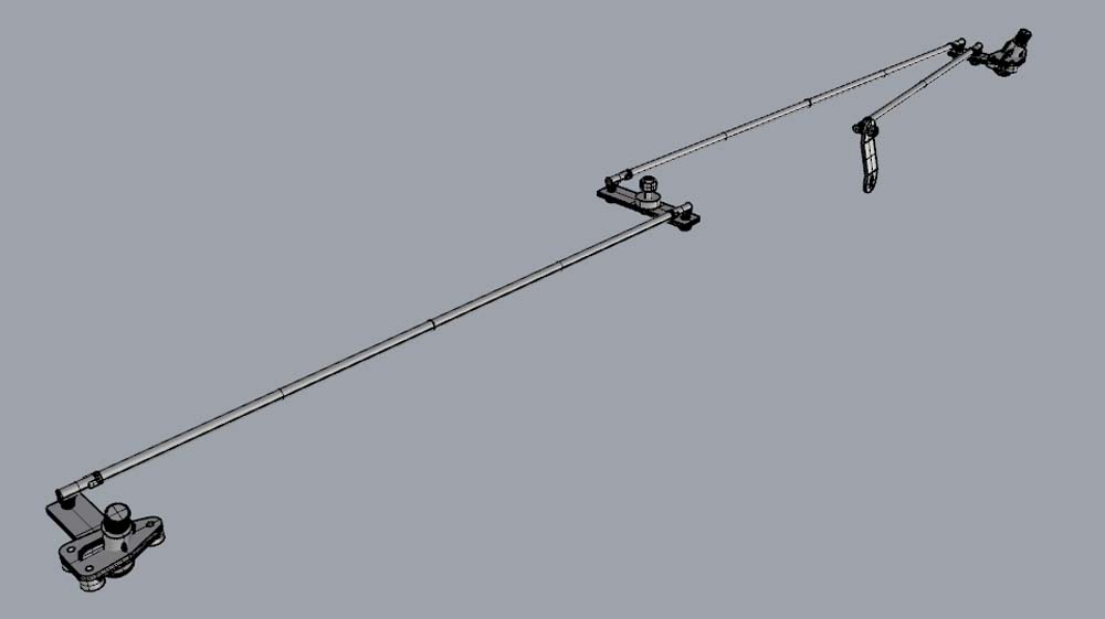
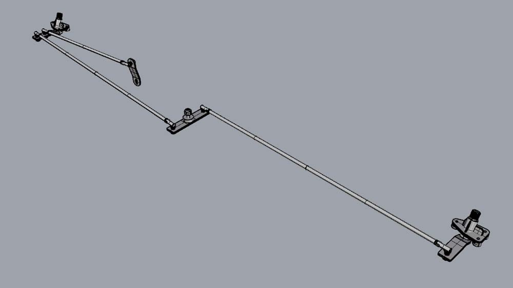
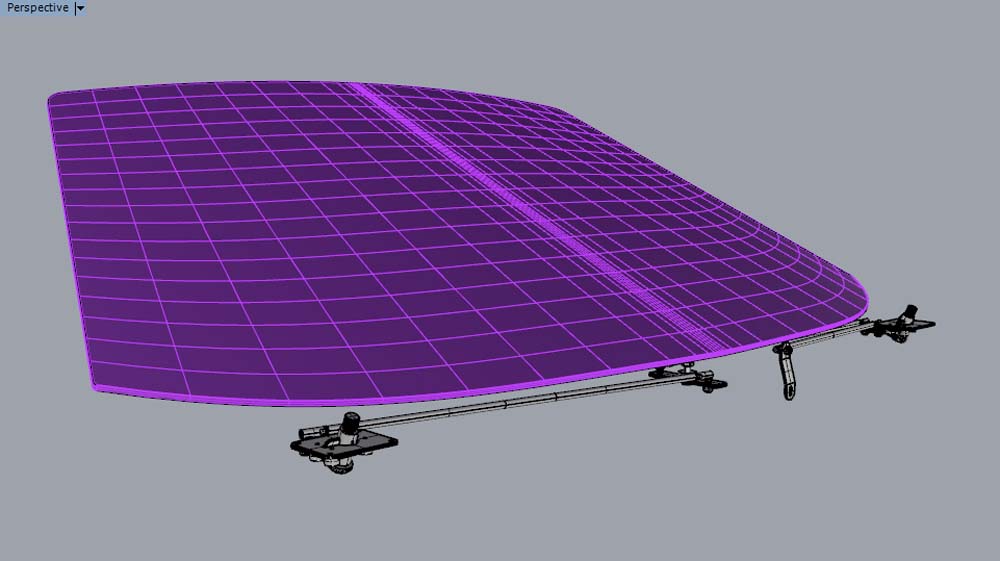
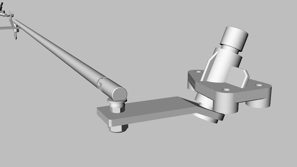
With all the basic components selected for this new wiper linkage arrangement, I set about designing the assembly in 3D. For those that have ever used McMaster Carr, you'll know how amazing their selection is for hardware and components. Another huge benefit to this supplier is that along almost everything they sell, they offer technical drawings in many 2D and 3D formats so all you need to do is down load them from their website. I am slowly making a library of every part, nut and bolt etc that I have used on this project so far. Here is my new wiper linkage design from different angles.
With all the basic components selected for this new wiper linkage arrangement, I set about designing the assembly in 3D. For those that have ever used McMaster Carr, you'll know how amazing their selection is for hardware and components. Another huge benefit to this supplier is that along almost everything they sell, they offer technical drawings in many 2D and 3D formats so all you need to do is down load them from their website. I am slowly making a library of every part, nut and bolt etc that I have used on this project so far. Here is my new wiper linkage design from different angles.
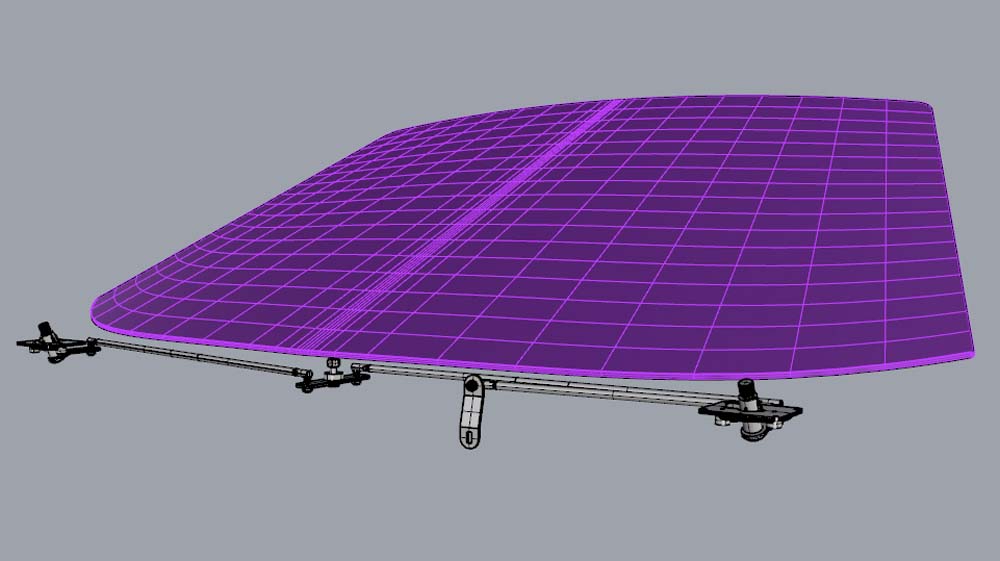
Here is what the new linkage looks like with the extended windshield added to the drawing.
Here are some close up images of the driver side and passenger side pivots with linkages attached.
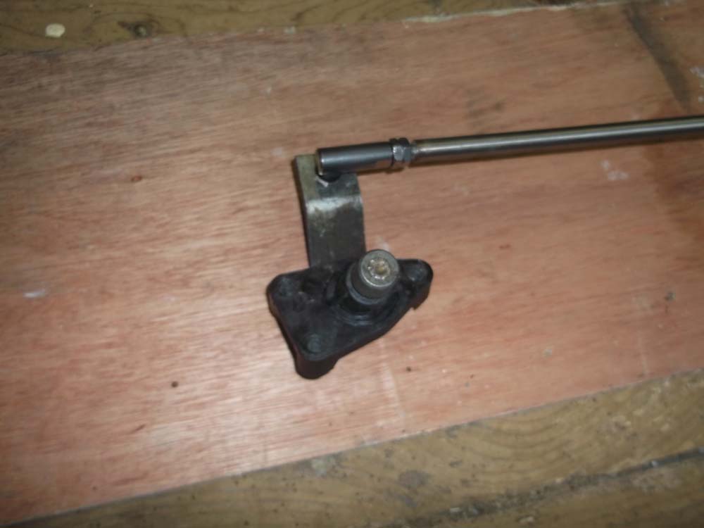
Here is what the actual parts look like assembled. The driver side pivot has the linkage from the motor as well as the linkage to the center pivot. I apologize for the poor photography.
Nov 18 2013
I should explain a little more about my new wiper linkage design, especially with regard to the center pivot point. As I have mentioned, with the new wiper linkage design having the wipers sweep toward each other, this necessitates changing the direct of the passenger side wiper from stock. In other to do this, the linkage between the driver side pivot and the passenger side must pass through an additional linkage arm with each attached at opposite ends of the additional pivot arm. This gives the desired effect of changing the direction of the passenger wiper in relation to the driver side wiper. It is the same effect achieved when you add a third idler gear in the middle of two other gears. The final output gear changes direction relative to the initial arrangement. My design takes advantage of the stock passenger side wiper pivot location in the center of the car and uses this location to mount the new additional center pivot point. With this in mind, I will show how I mounted the driver side and passenger side wiper pivots so that they are located outside the boundaries of the extended windshield. The new additional center pivot will remain inside the extended windshield boundary but that is fine as it will all be hidden inside the front cowl with all the linkages.
It goes without saying that my goal is to utilize the stock cowl arrangement to enclose all the new wiper linkages. For the most part, this should be a simple matter. As the driver side wiper mechanism has an adequate access opening to the cowl from inside the car, the only changes involve creating additional accesses to the cowl on the passenger side as there was no wiper mechanisms there in the stock arrangement. As well, I will add an additional access to the cowl from inside the car at the center pivot location to aide in assembly of the new mechanism.
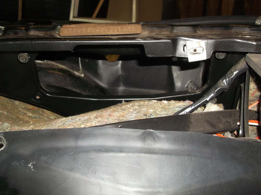
Here is the stock cowl opening on the driver side. I have already removed the access cover plate.
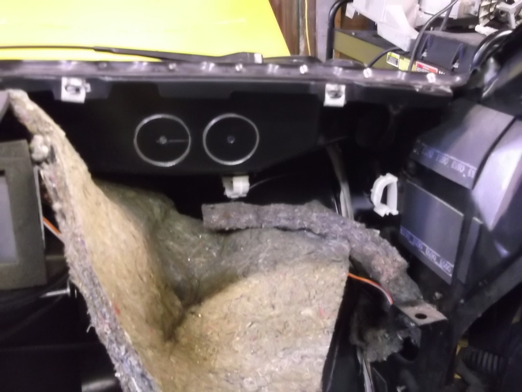
I added a similar access opening on the passenger side using a 2" hole saw to cut the ends of the opening and then removing the rest of the material with a zip wheel.
