Roll over hoops
Jan 21 2013
In the previous sub category of Rocker Reinforcement, I mentioned that the roof structure of the Fiero, like most cars, performs two important functions:
1. Contributes to the structural integrity of the entire chassis
2. Provides the occupants with some measure of protection during an accident
While the addition of the new rocker frames greatly improved the structural integrity of the chassis in the longitudinal direction, it is still necessary to improve the chassis structural integrity in the transverse direction. This is a function that the stock Fiero roof did well. As well, the stock roof offered protection to the occupants during a collision or roll over. However, as I plan to remove the roof structure during this build, it becomes necessary to design a new structure that will replace the transverse structure of the roof as well as provide some suitable level of protection to the occupants.
During the design phase of this structure, I had three requirements that I felt were important to meet:
1. The new structure must be fabricated completely prior to installation into the chassis
2. The new structure must tie as much of the stock structure together as possible and fit within the confines of the 355 body
3. The new structure must be aesthetically pleasing in relation to the body styling of the 355
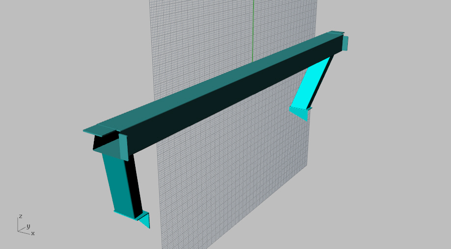
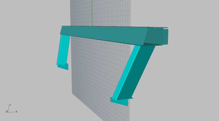
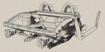
I decided that the new transverse structure would fit directly behind the top edge of the fire wall and tie the upper frame rails together. As well, the new structure would extend downward to connect to the lower frame rails. This would provide a secure foundation for the installation of two roll over hoops and distribute and loads into all four rear frame rails. Here is the design based on a 4" x 3" x 1/8" HSS (Hollow Structural Section) which had the forward edge sloped to match the angle of the fire wall. The vertical structural members are 3" x 1 1/2" x 1/8" HSS with a 1/8" plate bracket at the lower end.
In the previous sub category of Rocker Reinforcement, I mentioned that the roof structure of the Fiero, like most cars, performs two important functions:
1. Contributes to the structural integrity of the entire chassis
2. Provides the occupants with some measure of protection during an accident
While the addition of the new rocker frames greatly improved the structural integrity of the chassis in the longitudinal direction, it is still necessary to improve the chassis structural integrity in the transverse direction. This is a function that the stock Fiero roof did well. As well, the stock roof offered protection to the occupants during a collision or roll over. However, as I plan to remove the roof structure during this build, it becomes necessary to design a new structure that will replace the transverse structure of the roof as well as provide some suitable level of protection to the occupants.
During the design phase of this structure, I had three requirements that I felt were important to meet:
1. The new structure must be fabricated completely prior to installation into the chassis
2. The new structure must tie as much of the stock structure together as possible and fit within the confines of the 355 body
3. The new structure must be aesthetically pleasing in relation to the body styling of the 355
I decided that the new transverse structure would fit directly behind the top edge of the fire wall and tie the upper frame rails together. As well, the new structure would extend downward to connect to the lower frame rails. This would provide a secure foundation for the installation of two roll over hoops and distribute and loads into all four rear frame rails. Here is the design based on a 4" x 3" x 1/8" HSS (Hollow Structural Section) which had the forward edge sloped to match the angle of the fire wall. The vertical structural members are 3" x 1 1/2" x 1/8" HSS with a 1/8" plate bracket at the lower end.
|
|
April 13 2013
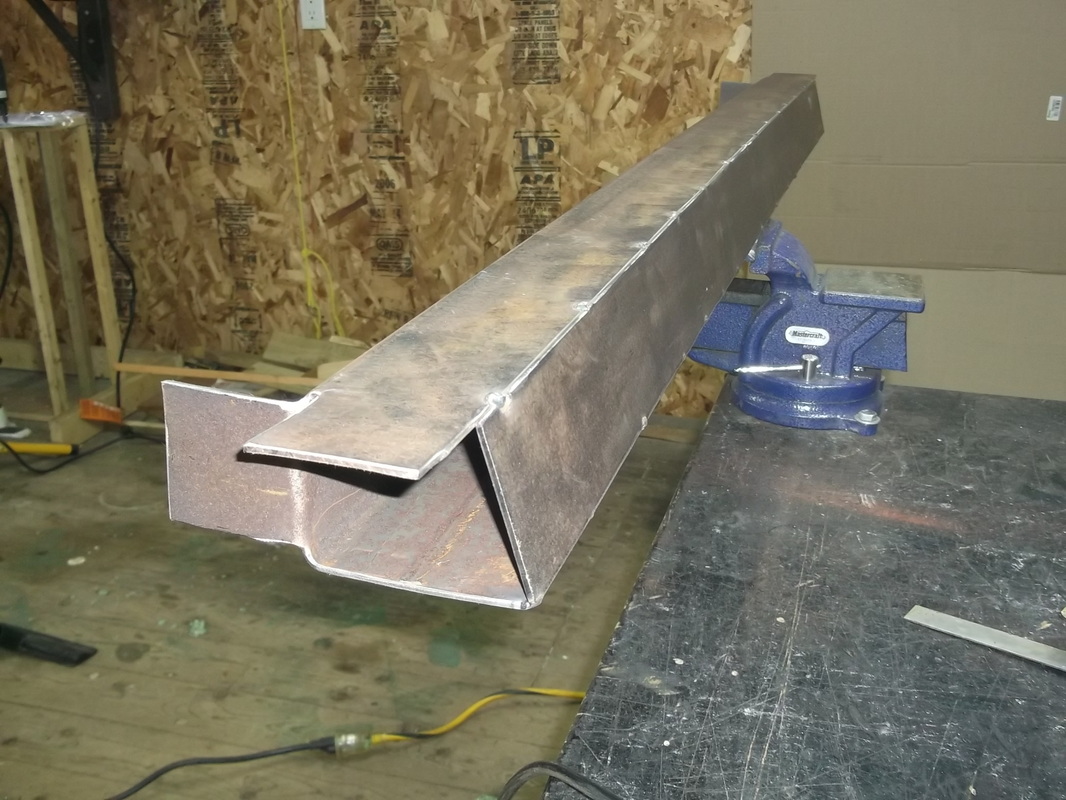
With the design work complete, I began fabrication of the structure. Remember, one of my goals is to have a structure that can be fabricated completely and then installed in the chassis.
With the design work complete, I began fabrication of the structure. Remember, one of my goals is to have a structure that can be fabricated completely and then installed in the chassis.
|
|
|
|
June 1 2013
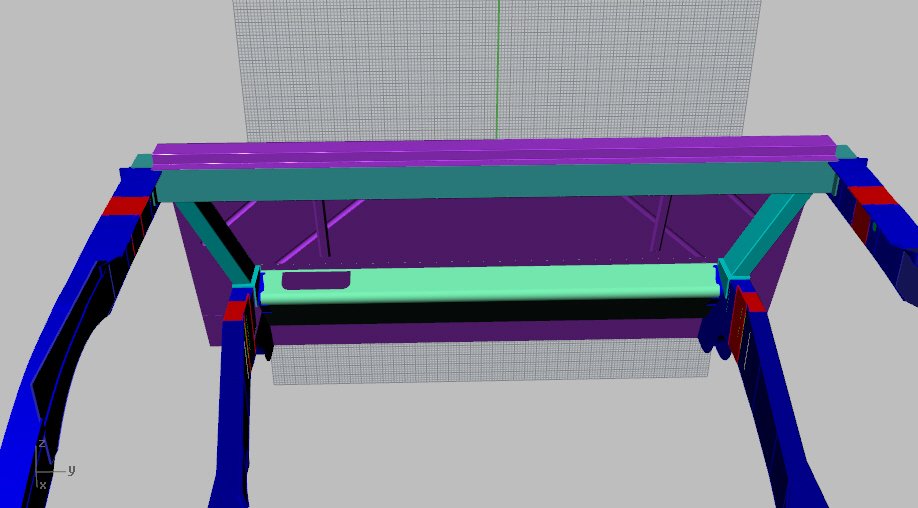
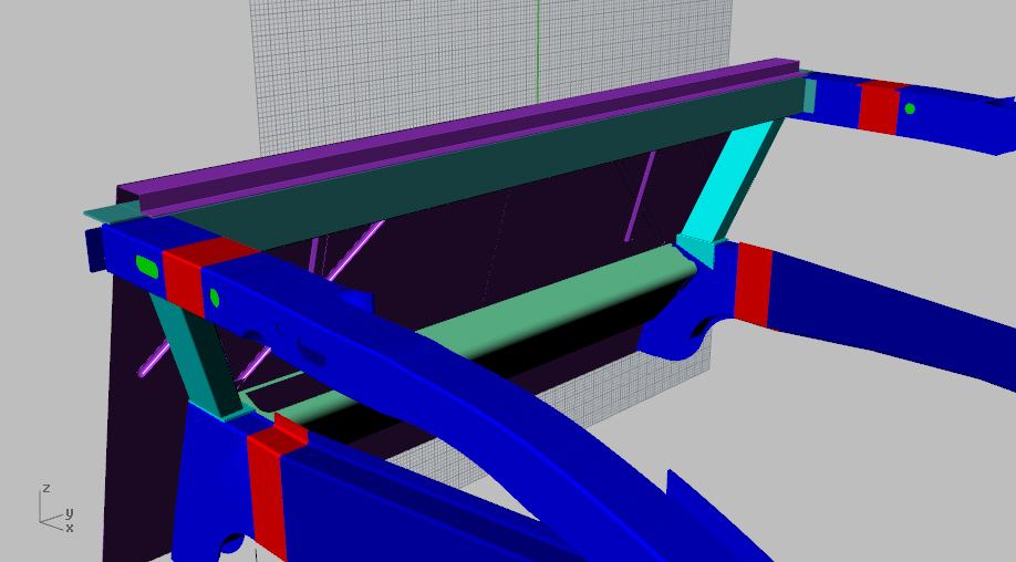
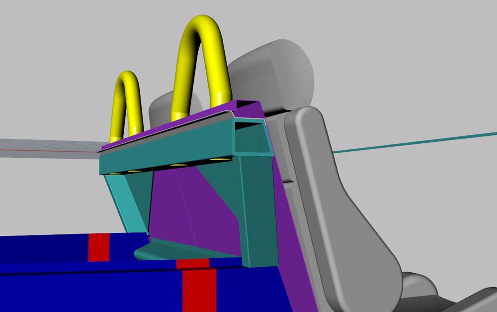
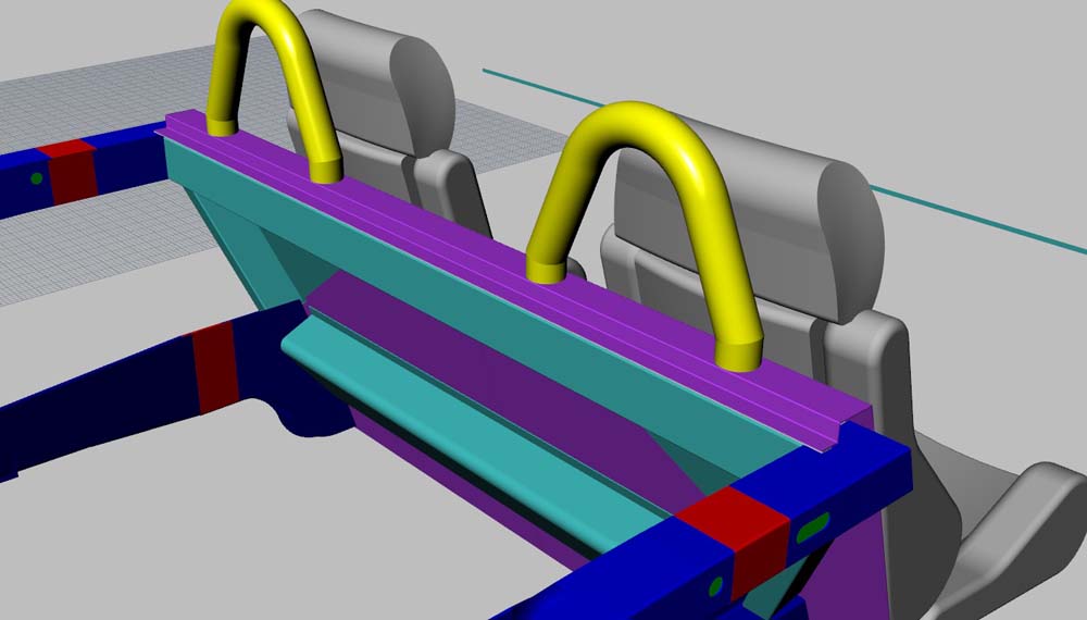
With the transverse frame fabricated and ready to install in the chassis, it was time to consider the roll over protection. I designed a set of hoops that would be secured into the transverse frame and would be positioned just high enough to protect the driver and passenger. I think the design also worked well with the 355 body style despite the fact that the actual Ferrari 355 did not come with roll over hoops. Here is the design of the hoops. I went with 1 1/2" Sch 40 Seamless DOM Pipe ASTM A-106. This gives a O.D of 1 7/8". The reason I went with pipe and not tubing is because I don't have a 2" tubing die for the hydraulic tubing bender. The 1 1/2" pipe die had a radius of 4" so that also dictated the general shape of the hoop.
With the transverse frame fabricated and ready to install in the chassis, it was time to consider the roll over protection. I designed a set of hoops that would be secured into the transverse frame and would be positioned just high enough to protect the driver and passenger. I think the design also worked well with the 355 body style despite the fact that the actual Ferrari 355 did not come with roll over hoops. Here is the design of the hoops. I went with 1 1/2" Sch 40 Seamless DOM Pipe ASTM A-106. This gives a O.D of 1 7/8". The reason I went with pipe and not tubing is because I don't have a 2" tubing die for the hydraulic tubing bender. The 1 1/2" pipe die had a radius of 4" so that also dictated the general shape of the hoop.
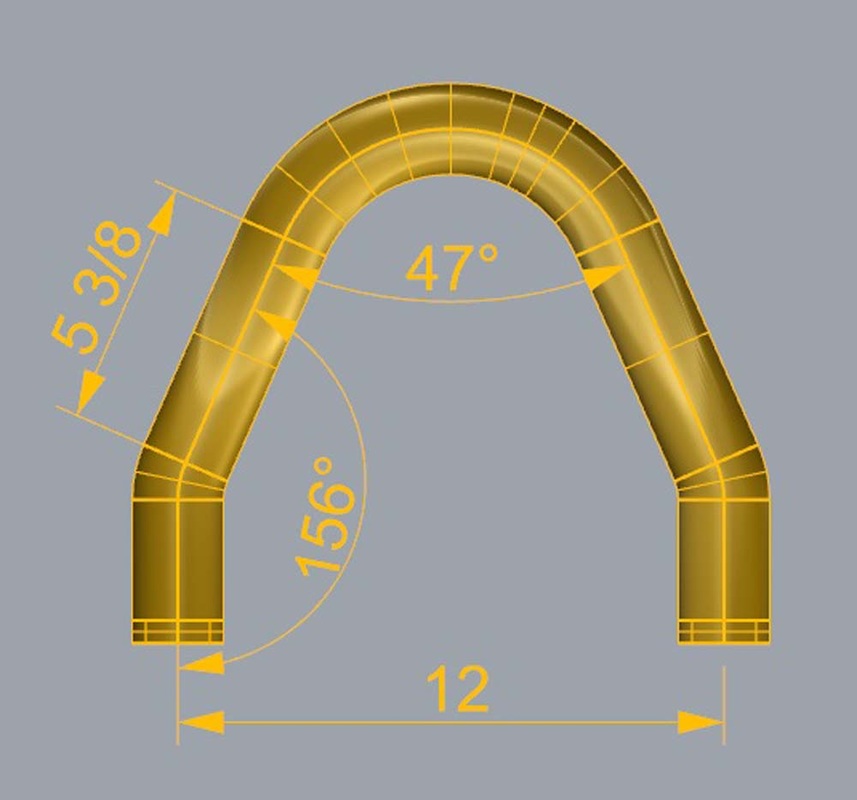
Here are a few images of the hoops located in the transverse frame. I agonized long and hard over the exact location and height of the hoops until I finally settled on this.
|
|
|
|
June 8 2013
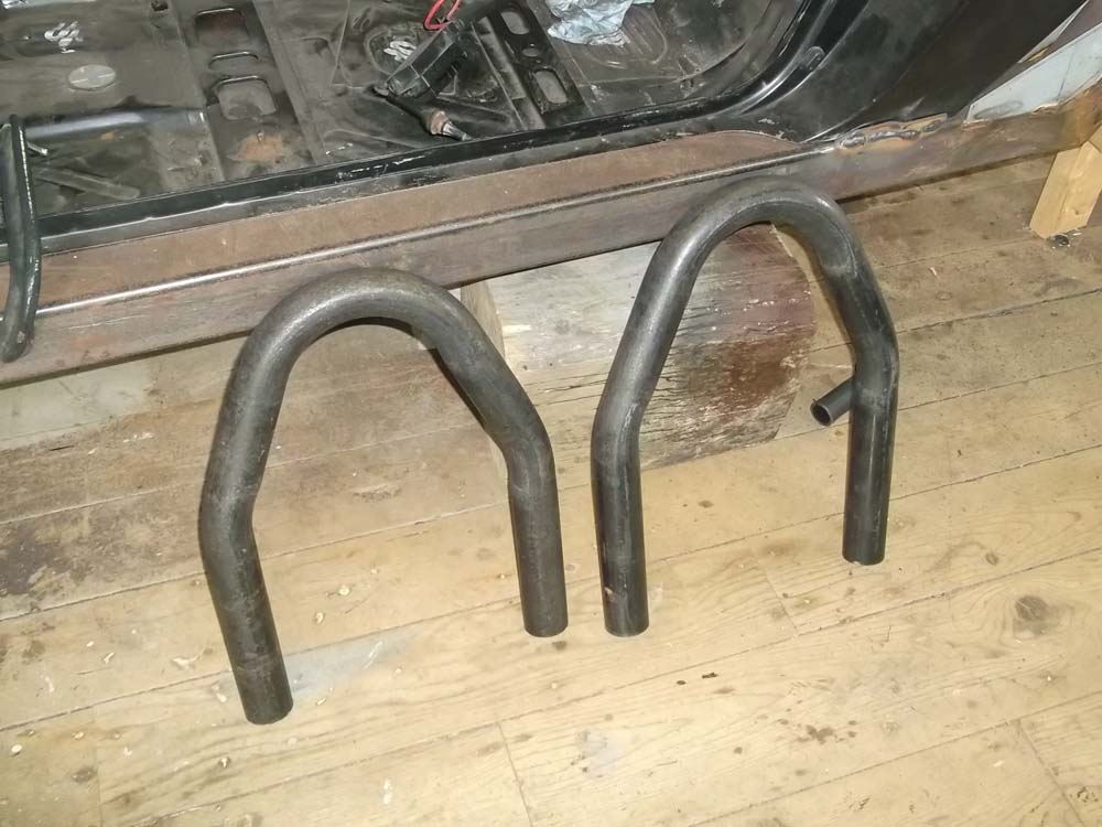
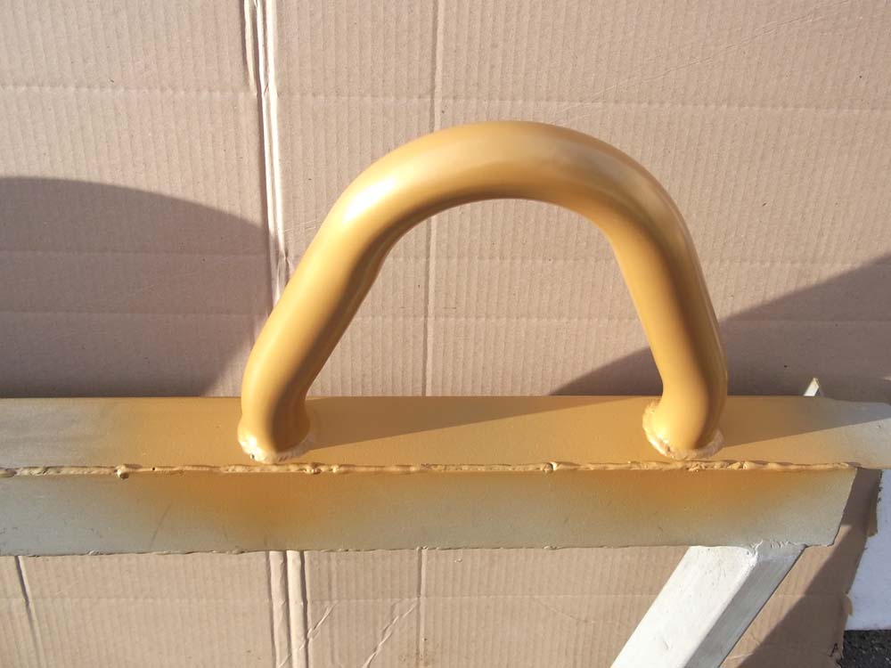
As I mentioned above, I formed the hoops on a computerized hydraulic bender but it was still alot of work to get them exactly symmetrical. I actually ended up making 4 pieces so that I had a couple spares in case things went horribly wrong during installation. Here are the two I chose to use. I was very happy with how they turned out.
As I mentioned above, I formed the hoops on a computerized hydraulic bender but it was still alot of work to get them exactly symmetrical. I actually ended up making 4 pieces so that I had a couple spares in case things went horribly wrong during installation. Here are the two I chose to use. I was very happy with how they turned out.
June 18 2013
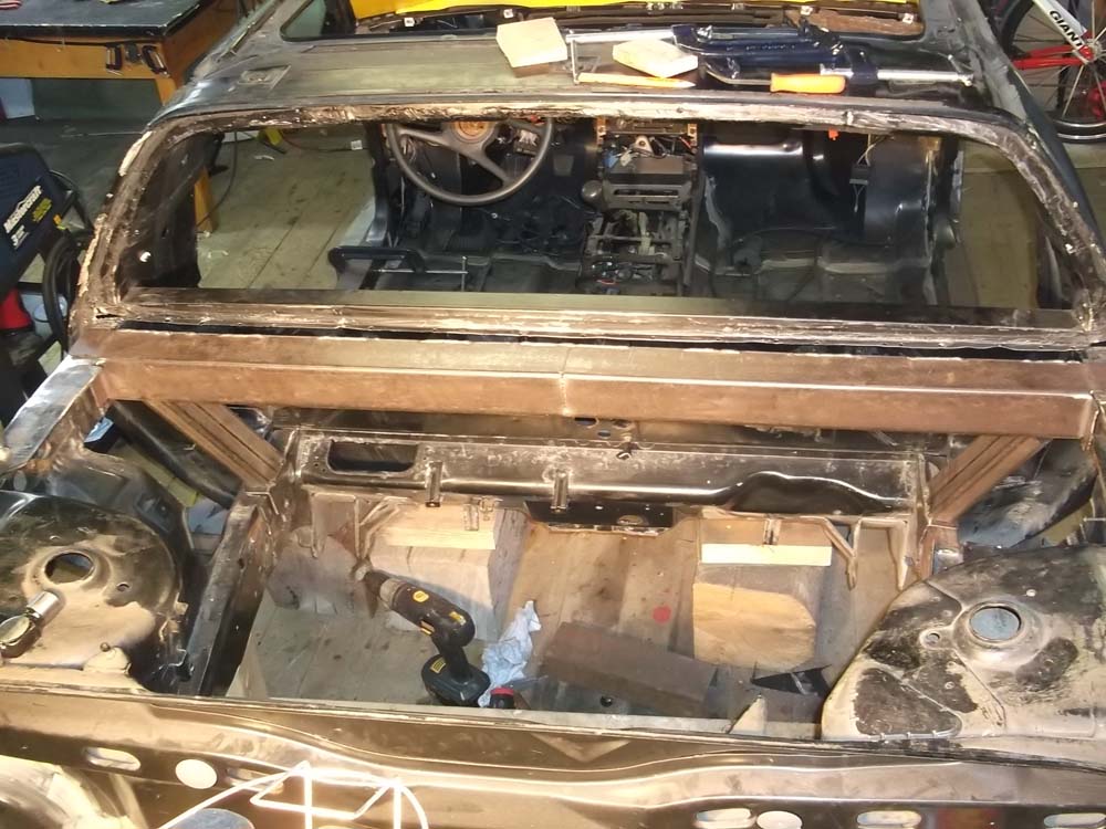
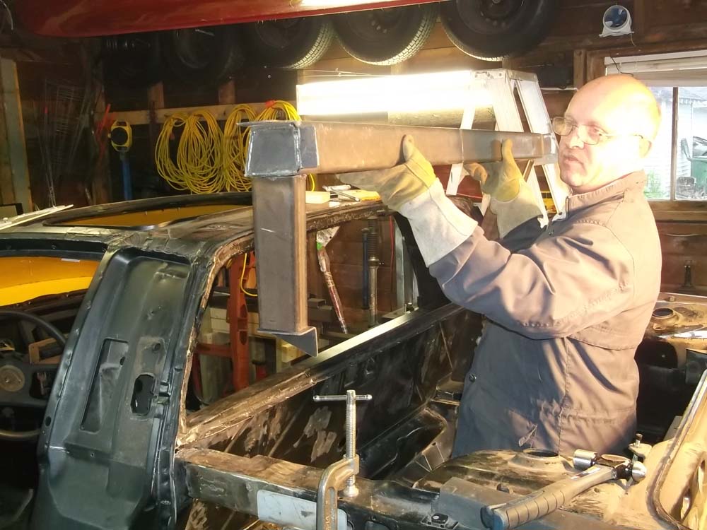
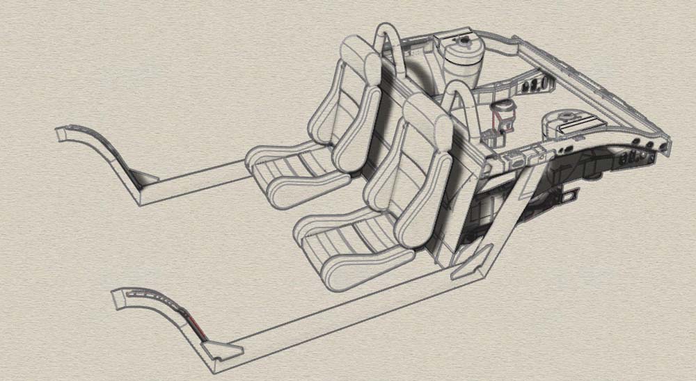
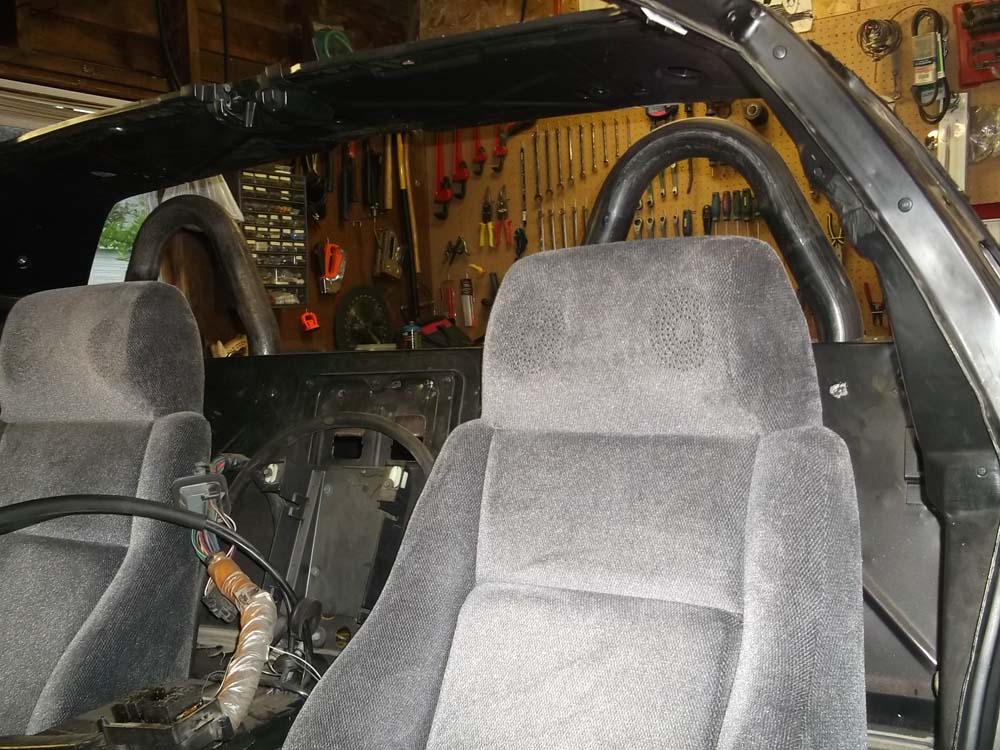
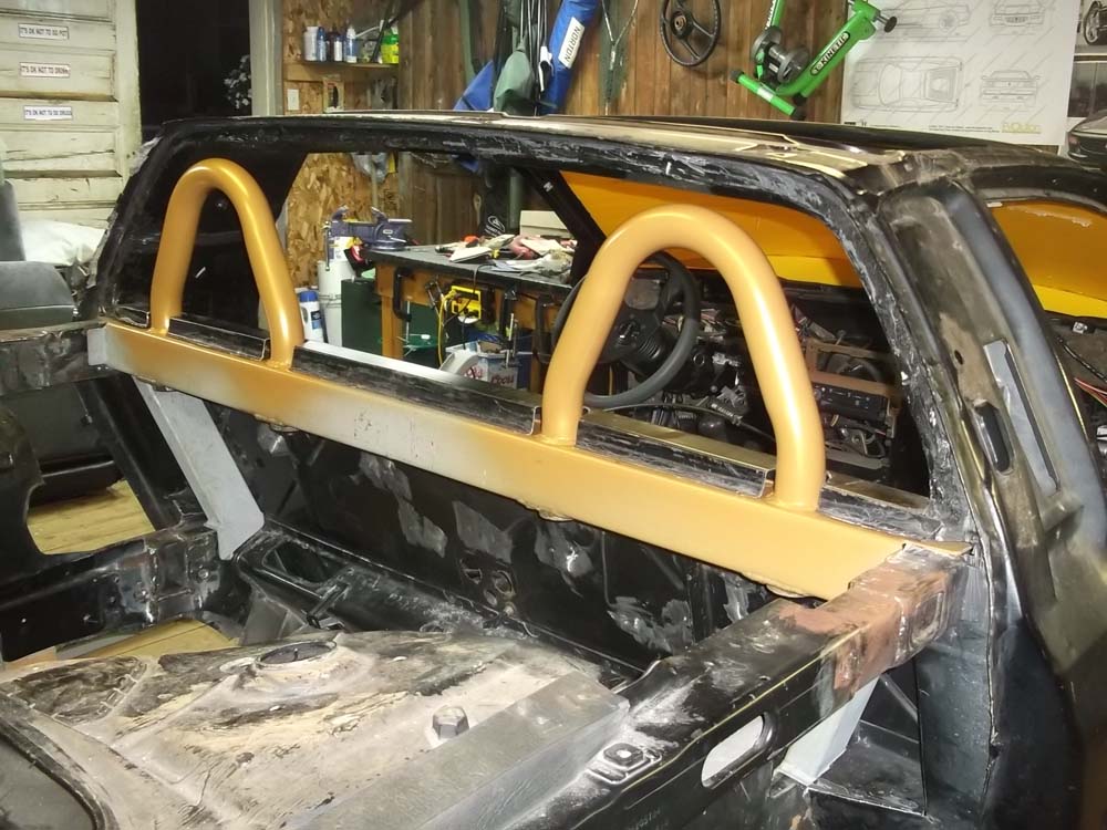
With the hoops made, the next step was to try them in position on the chassis and conform that they would look as good as they did in the design. I put the seats back in the car as it was important that they be aligned transversely and symmetrical with the chassis as well as be set to the right height in relation to the head rests.
With the hoops made, the next step was to try them in position on the chassis and conform that they would look as good as they did in the design. I put the seats back in the car as it was important that they be aligned transversely and symmetrical with the chassis as well as be set to the right height in relation to the head rests.
|


|

July 4 2013
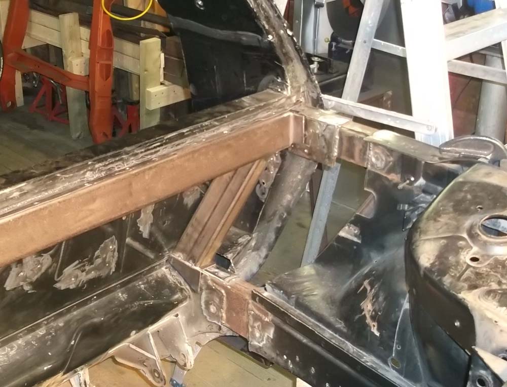
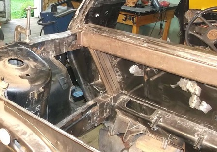
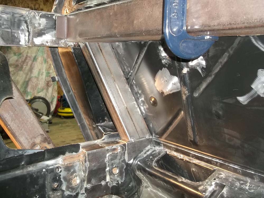
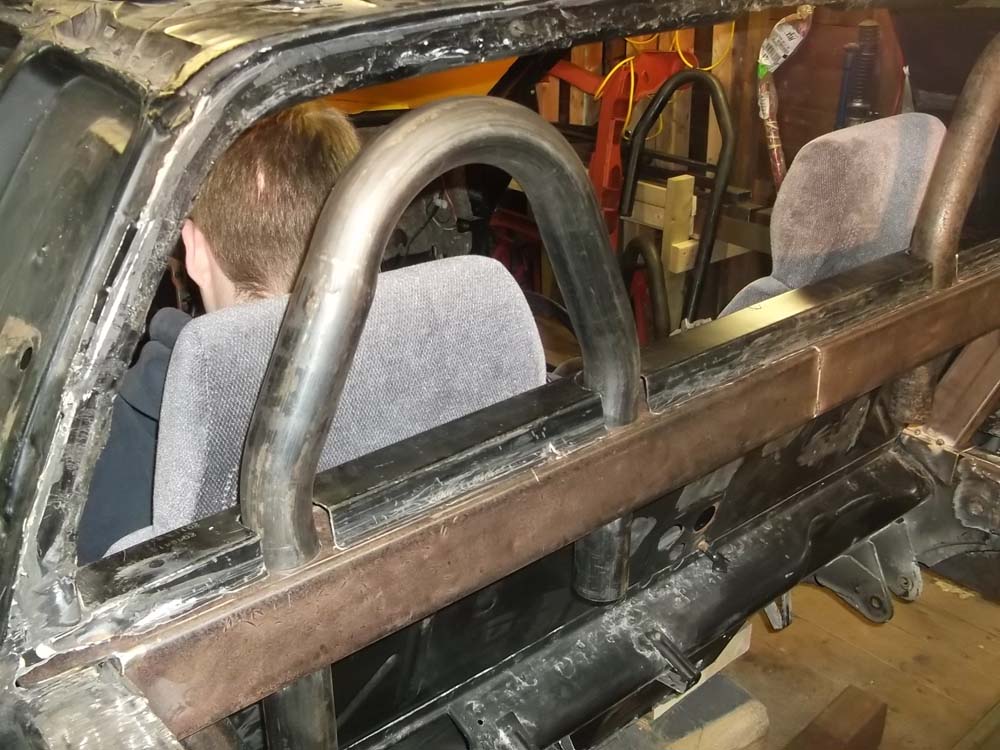
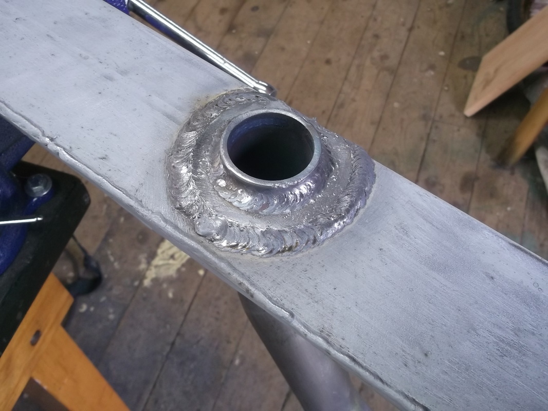
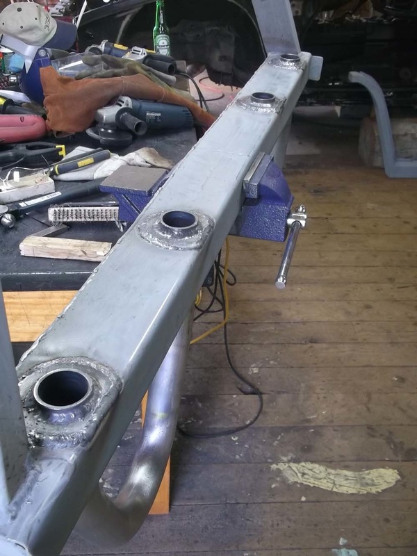
With the location decided, I drilled the transverse frame through the top and bottom and allowed the hoops to pass right through the frame. I was then able to slide them up and down until I was happy with the height. It was then time to weld them in position. Remember that I made this frame to be assembled completely before final installation. This includes the hoops and it allowed a quality welding job.
With the location decided, I drilled the transverse frame through the top and bottom and allowed the hoops to pass right through the frame. I was then able to slide them up and down until I was happy with the height. It was then time to weld them in position. Remember that I made this frame to be assembled completely before final installation. This includes the hoops and it allowed a quality welding job.

|

|
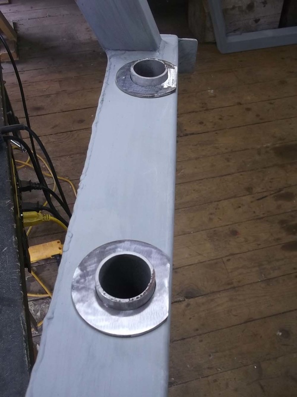
On the underside of the frame where the ends of the hoops pass through the frame, I reinforced the ends with circular plates.

|
|
July 7 2013
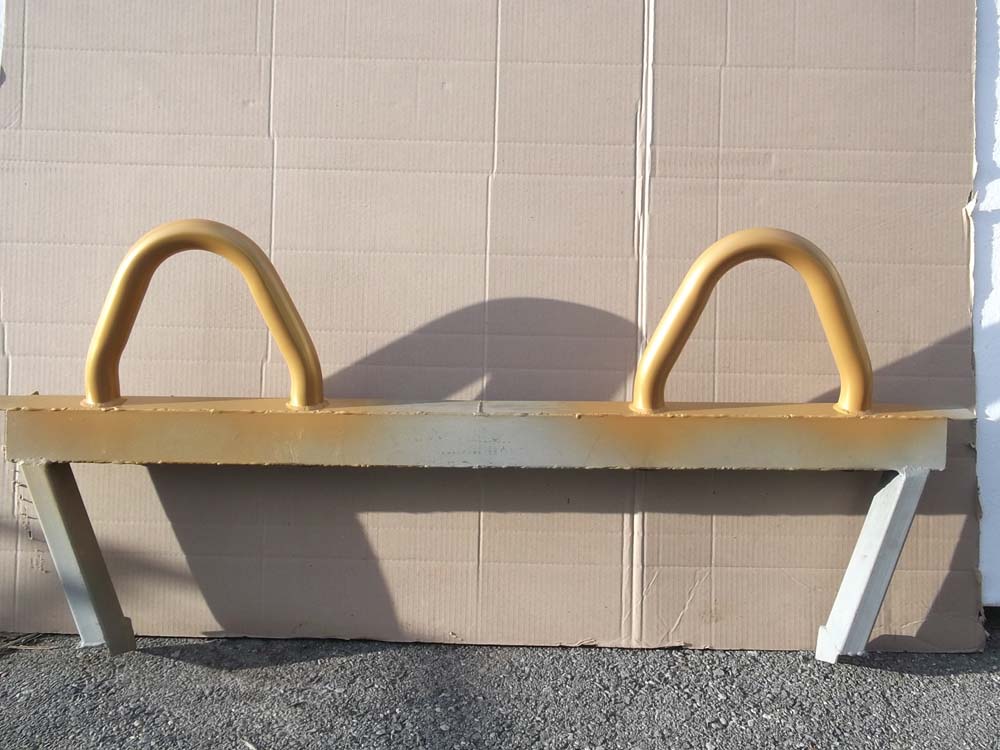
With the transverse frame fully welded and ready for installation, there was one more step I wanted to complete. As you may have guessed by now, my car is going to be black..... all black...... well almost all. I have decided to do an accent colour of gold. I have planned on having various parts of the car powder coated and the actual colour code is called Gold Nugget. The first parts to be powder coated will be the roll over hoops. So I did a test on one of the spare hoops to see how it would look. Not only did I want to test the colour but I wanted to test which finish I wanted. Here is a picture showing them in the 4 stages, formed, sanded, sand blasted and then powder coated. The two shorter hoops are the ones I used and this picture was actually taken just before they were welded into the transverse frame in the steps shown above.
With the transverse frame fully welded and ready for installation, there was one more step I wanted to complete. As you may have guessed by now, my car is going to be black..... all black...... well almost all. I have decided to do an accent colour of gold. I have planned on having various parts of the car powder coated and the actual colour code is called Gold Nugget. The first parts to be powder coated will be the roll over hoops. So I did a test on one of the spare hoops to see how it would look. Not only did I want to test the colour but I wanted to test which finish I wanted. Here is a picture showing them in the 4 stages, formed, sanded, sand blasted and then powder coated. The two shorter hoops are the ones I used and this picture was actually taken just before they were welded into the transverse frame in the steps shown above.
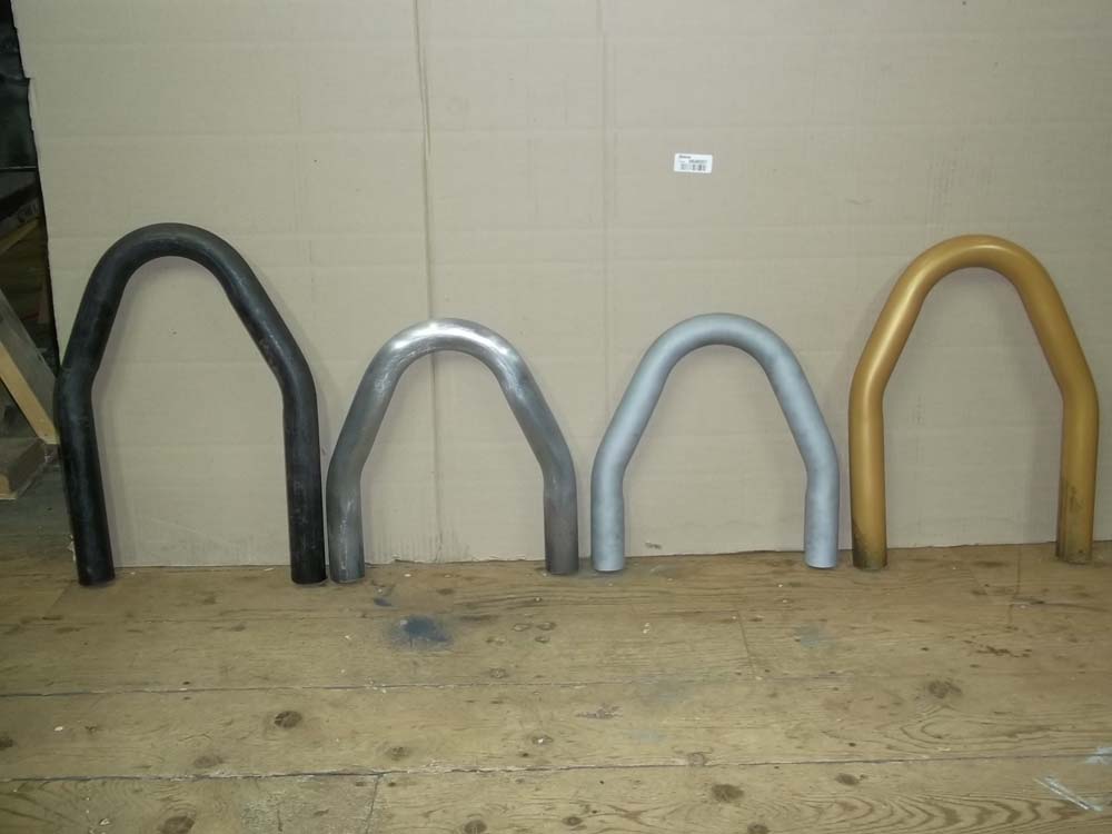
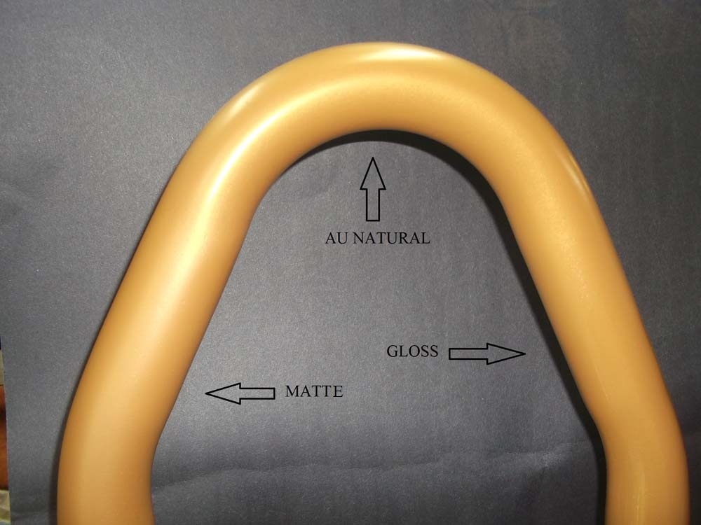
Here is a close up showing the three possible finishes. I went with au natural because the satin finish will look the best with the satin black finish on the car.
|
|
July 13 2013
And here is the final assembly powder coated and positioned in the chassis ready for final welding.
And here is the final assembly powder coated and positioned in the chassis ready for final welding.
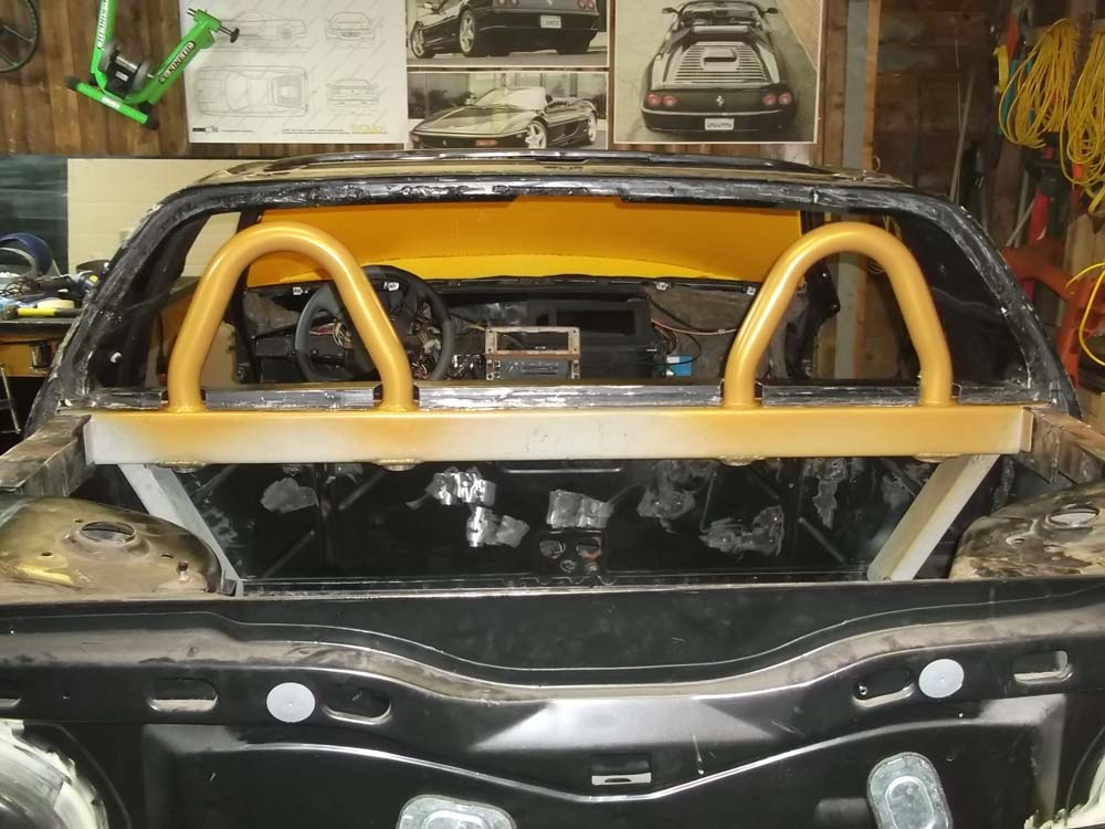
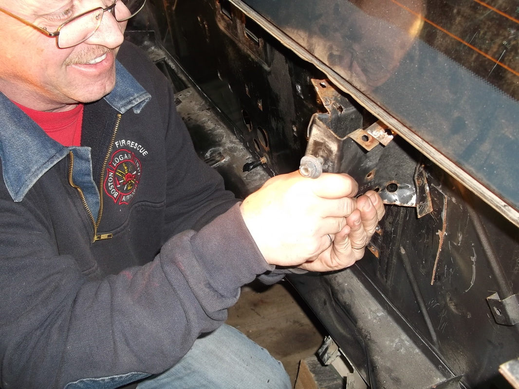
For those of you familiar with the Fiero construction, you'll notice that I removed the stock engine compartment hinges and some of the extra reinforcement along the underside of the upper edge of the fire wall. Oh ya, and we removed the rear window. That was not pretty to see so I didn't take any pictures. Please know, we tried our best to get the window out in one piece....but it wasn't to be.

|
|
