rocker reinforcement
Sept 28 2012
As you may have gathered by now, my plans for this project car include making it into a convertible or a spider. I would have to say that this task is probably one of the most challenging and involved aspects of my build project to date and will certainly rival the engine swap and construction of the body which will come later.
Like any car on the road today, the Fiero roof structure performs two important tasks:
1. Contributes to the structural integrity of the entire chassis
2. Provides the occupants with some measure of protection during an accident
For this reason, I have broken down my tasks accordingly so that the act of removing the actual roof will be proceeded by two separate but related operations:
1. Design, fabricate and install the chassis reinforcements
2. Design, fabricate and install occupant roll over protection
The reason I am doing these two tasks prior to removing the roof is quite simple. In order to ensure that the remaining structure of the chassis remains as straight, square and as level as the stock chassis was designed to be, it is necessary to add the additional structure before any existing structure is removed. This prevents the chassis, during construction, from even being in a significantly weaker condition than is was ever designed to be in. As well of course, it will be important to have the chassis adequately supported at all times and conduct regular checks of the chassis alignment during every step of the operation. By doing all this, I hope to minimize the risk of having the chassis hog, sag or twist during construction.
So, with all that said, I will begin my description of the rocker reinforcement procedure.
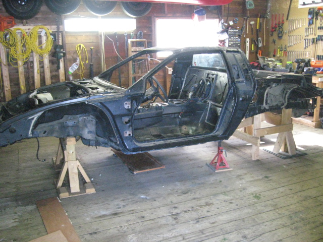
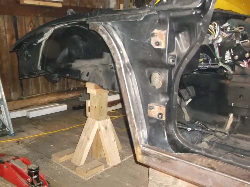
As I said previously, it's important to have the chassis well supported, level and straight. Here is my chassis prior to beginning. You will notice as we progress, that I also added solid blocks of wood under the passenger space for additional support.
As you may have gathered by now, my plans for this project car include making it into a convertible or a spider. I would have to say that this task is probably one of the most challenging and involved aspects of my build project to date and will certainly rival the engine swap and construction of the body which will come later.
Like any car on the road today, the Fiero roof structure performs two important tasks:
1. Contributes to the structural integrity of the entire chassis
2. Provides the occupants with some measure of protection during an accident
For this reason, I have broken down my tasks accordingly so that the act of removing the actual roof will be proceeded by two separate but related operations:
1. Design, fabricate and install the chassis reinforcements
2. Design, fabricate and install occupant roll over protection
The reason I am doing these two tasks prior to removing the roof is quite simple. In order to ensure that the remaining structure of the chassis remains as straight, square and as level as the stock chassis was designed to be, it is necessary to add the additional structure before any existing structure is removed. This prevents the chassis, during construction, from even being in a significantly weaker condition than is was ever designed to be in. As well of course, it will be important to have the chassis adequately supported at all times and conduct regular checks of the chassis alignment during every step of the operation. By doing all this, I hope to minimize the risk of having the chassis hog, sag or twist during construction.
So, with all that said, I will begin my description of the rocker reinforcement procedure.
As I said previously, it's important to have the chassis well supported, level and straight. Here is my chassis prior to beginning. You will notice as we progress, that I also added solid blocks of wood under the passenger space for additional support.
Like everything in life, there are many ways to do things to achieve an common end result and reinforcing a Fiero chassis is no different. After researching several other well documented build thread by people who have done this task well ahead of me, I decided on 4 key points that I wanted to achieve.
1. Any additional structure added to the chassis would not result in less ground clearance than the stock chassis already had.
2. The additional structure would extend as far forward and rearward as practical and tie as much of the stock structure together as practical.
3. The additional structure would be atleast equal in strength (preferably more) in all axes as the structure that will be removed.
4. The additional structure would not interfere with the 355 body style I had planned to use nor would it impinge on the passenger compartment.
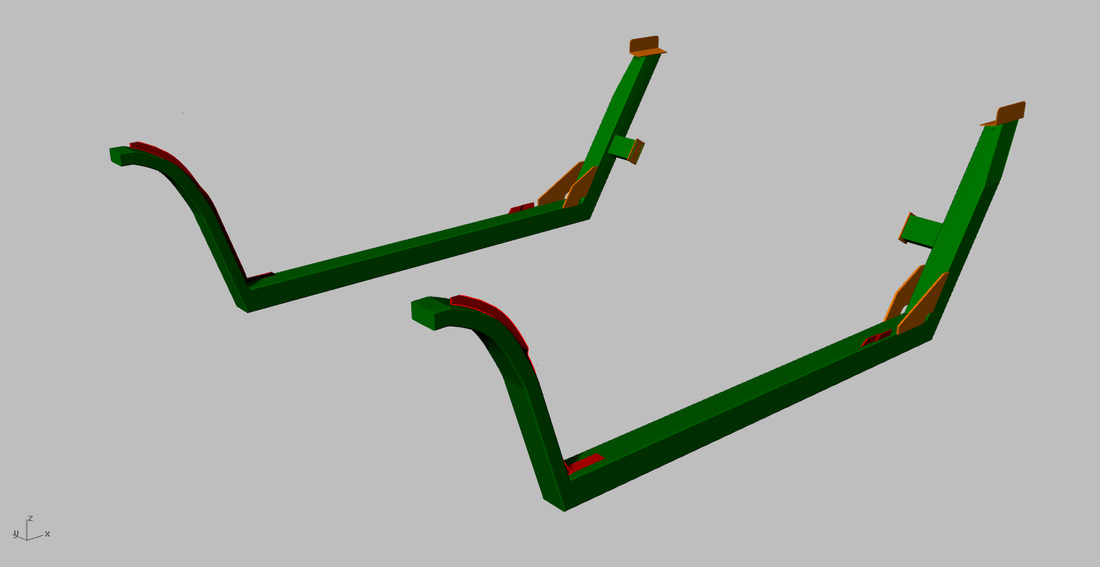
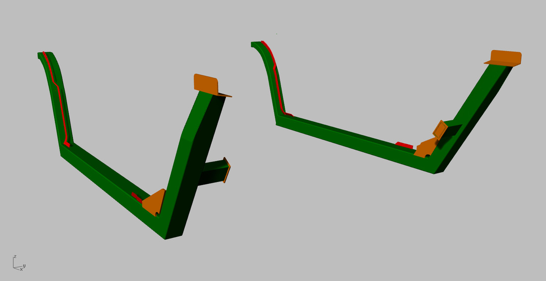
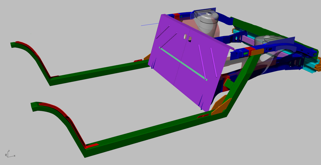
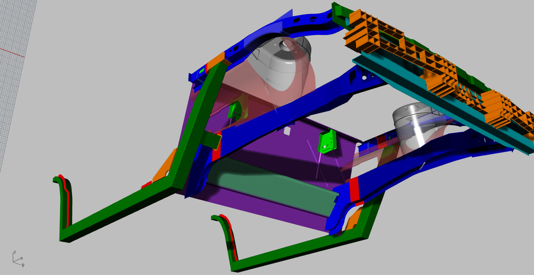
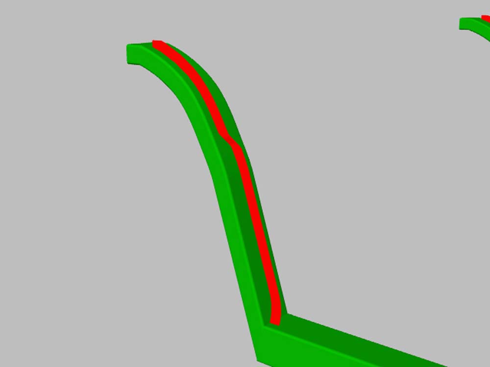
With all this in mind, I decided to reinforce the stock rocker structure by removing as much of the stock sheet metal structure as necessary in order the get the new structure as close to solid structure of the chassis as possible to allow adequate welding. I also decided to extend as far forward as possible to reinforce the forward edge of the A pillar and as far rearward as possible to reinforce the B pillar and tie the new structure into the rear upper and lower frame rails. By reinforcing the A pillar in this way, the door hinge mounting points would not be effected but would increase their strength as well, I would avoid having the new structure impinge in the front wheel well. Then proceeding rearward and capturing the B pillar with the structure meant that in turn, the rear firewall would also be strengthened. Having the new structure proceed past the B pillar as far rearward as possible without impinging into the rear wheel well and then heading upward so that the structure could be secured to the lower frame rail and then ending at the upper frame rail. Here is my design of the structure standing alone and then with the new structure integrated with the chassis.
1. Any additional structure added to the chassis would not result in less ground clearance than the stock chassis already had.
2. The additional structure would extend as far forward and rearward as practical and tie as much of the stock structure together as practical.
3. The additional structure would be atleast equal in strength (preferably more) in all axes as the structure that will be removed.
4. The additional structure would not interfere with the 355 body style I had planned to use nor would it impinge on the passenger compartment.
With all this in mind, I decided to reinforce the stock rocker structure by removing as much of the stock sheet metal structure as necessary in order the get the new structure as close to solid structure of the chassis as possible to allow adequate welding. I also decided to extend as far forward as possible to reinforce the forward edge of the A pillar and as far rearward as possible to reinforce the B pillar and tie the new structure into the rear upper and lower frame rails. By reinforcing the A pillar in this way, the door hinge mounting points would not be effected but would increase their strength as well, I would avoid having the new structure impinge in the front wheel well. Then proceeding rearward and capturing the B pillar with the structure meant that in turn, the rear firewall would also be strengthened. Having the new structure proceed past the B pillar as far rearward as possible without impinging into the rear wheel well and then heading upward so that the structure could be secured to the lower frame rail and then ending at the upper frame rail. Here is my design of the structure standing alone and then with the new structure integrated with the chassis.
|
|
Oct 15 2012
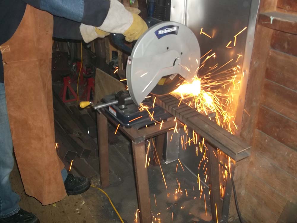
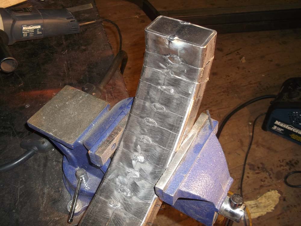
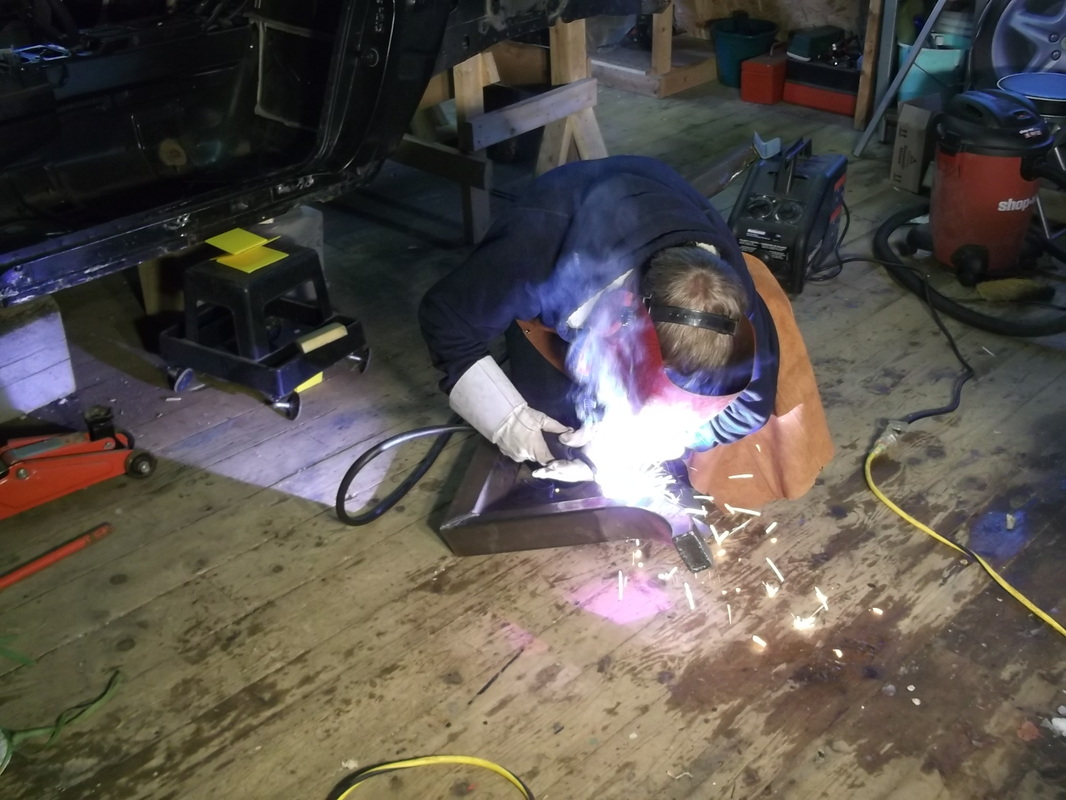
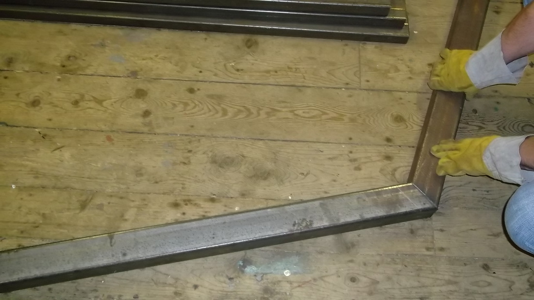
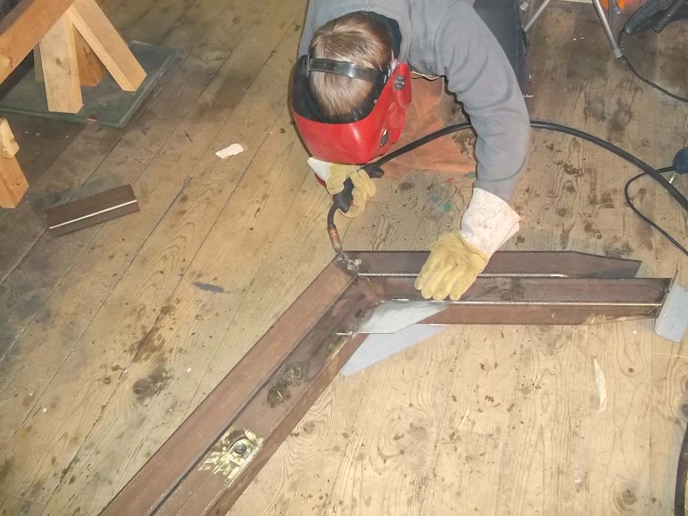
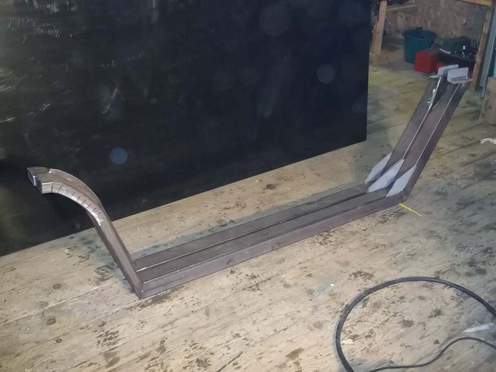
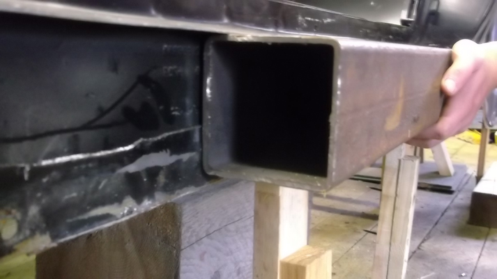
The new rocker structure was fabricated from 4" x 4" x 1/8" HSS steel for the main horizontal frame and 2" x 4" x 1/8" for the forward structure around the wheel well / A pillar. At the rear end of the frame, the 4" x 4" was tapered down to align with the upper rear sub frame. I added gussets at the B pillar where the frame direction changed. I also added a section of 2" x 4" x 1/8" HSS to connect the new frame to the lower rear sub frame as well. Here are a series of pictures showing fabrication of the new rocker frame.
The new rocker structure was fabricated from 4" x 4" x 1/8" HSS steel for the main horizontal frame and 2" x 4" x 1/8" for the forward structure around the wheel well / A pillar. At the rear end of the frame, the 4" x 4" was tapered down to align with the upper rear sub frame. I added gussets at the B pillar where the frame direction changed. I also added a section of 2" x 4" x 1/8" HSS to connect the new frame to the lower rear sub frame as well. Here are a series of pictures showing fabrication of the new rocker frame.
|

|
Dec 11 2012
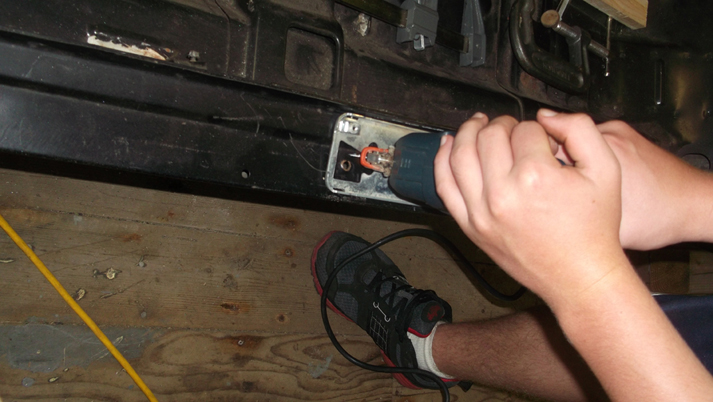
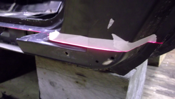
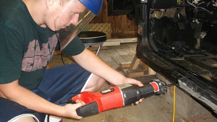
With the two new frames fabricated, it was now time to remove the unnecessary stock rocker frames. As I had mentioned earlier, one of the objectives of the new frame was to not reduce the overall ground clearance of the car. With this in mind, I laid out the lines to follow while cutting. For this operation, I used a laser to shoot a level line along the chassis. The benefit of the laser is that is scribes a level line over the compound curves of the stock sheet metal. I added masking tape to highlight the line so I could see it while cutting with the jigsaw and reciprocating saw. As you can see in these pictures, I had already started cutting alone the line before I remembered to take a picture. Oops :)
With the two new frames fabricated, it was now time to remove the unnecessary stock rocker frames. As I had mentioned earlier, one of the objectives of the new frame was to not reduce the overall ground clearance of the car. With this in mind, I laid out the lines to follow while cutting. For this operation, I used a laser to shoot a level line along the chassis. The benefit of the laser is that is scribes a level line over the compound curves of the stock sheet metal. I added masking tape to highlight the line so I could see it while cutting with the jigsaw and reciprocating saw. As you can see in these pictures, I had already started cutting alone the line before I remembered to take a picture. Oops :)

|
|
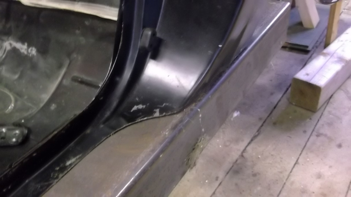
With the stock rockers removed, I test did a test fit at the A pillar and pillar to see how the profile fit the new square tubing frame. I was very happy with the fit and the tight joint would make welding much easier.


|
|
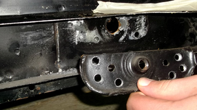
Before the new frame was fitted, it was necessary to remove the threaded seat belt anchor point that was spot welded inside the stock rocker frame. This piece would be cut smaller and then welded into the new frame to provide an anchor point for the new seatbelts one day.

|
|

|
Jan 22 2013
The next step is to install the new frames into the chassis. The frames were designed so that they could be fully welded prior to installation into the chassis in one piece. To assist in connecting / welding the new frame, it was necessary to add a 1" x 1/8" flange to the frame along the interface edge with the A pillar.
The next step is to install the new frames into the chassis. The frames were designed so that they could be fully welded prior to installation into the chassis in one piece. To assist in connecting / welding the new frame, it was necessary to add a 1" x 1/8" flange to the frame along the interface edge with the A pillar.
|

|
April 1 2013
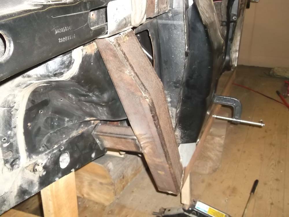
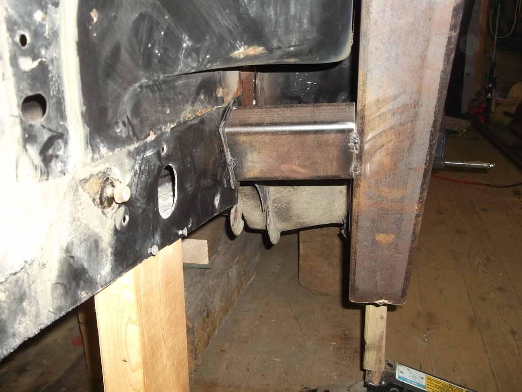
As I had mentioned, I added a structural connection between the new rocker frame and the lower rear frame rail as well as the end connection with the upper frame rail.
As I had mentioned, I added a structural connection between the new rocker frame and the lower rear frame rail as well as the end connection with the upper frame rail.
|
|
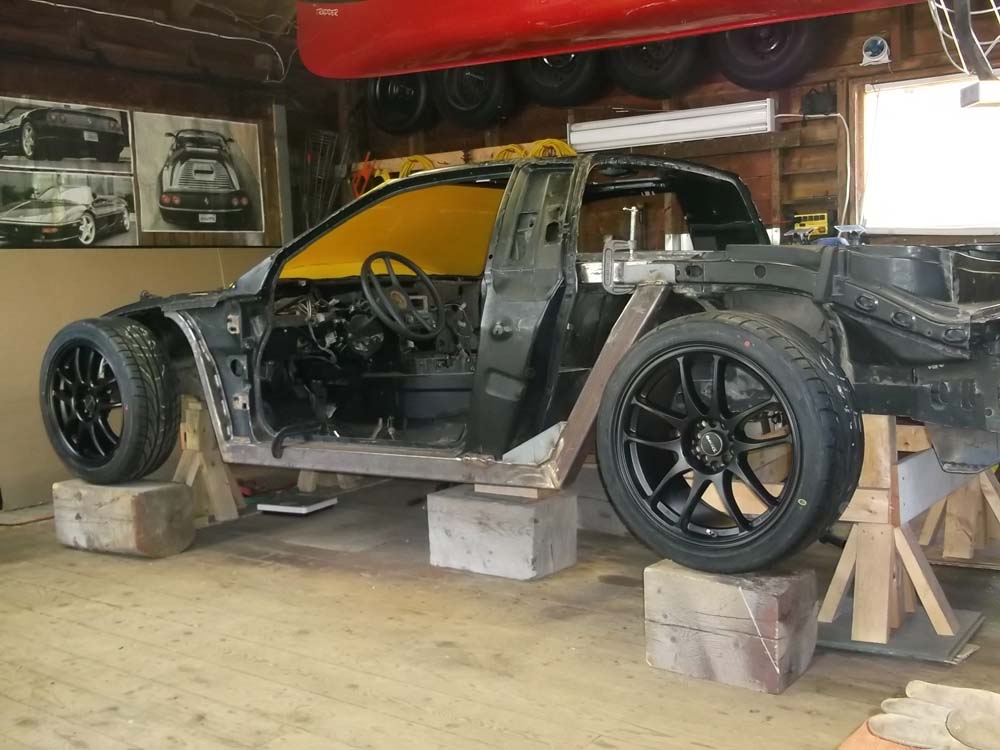
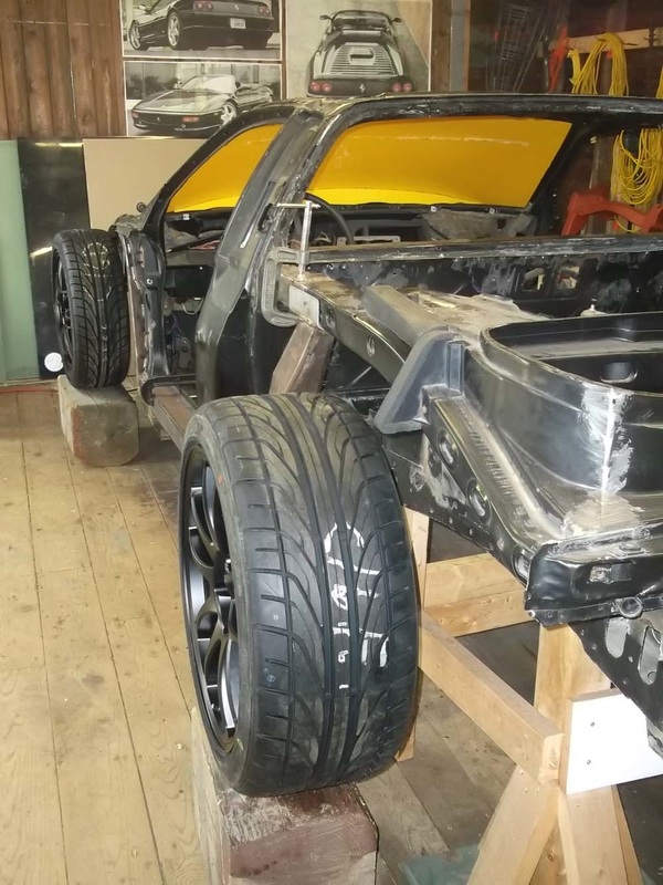
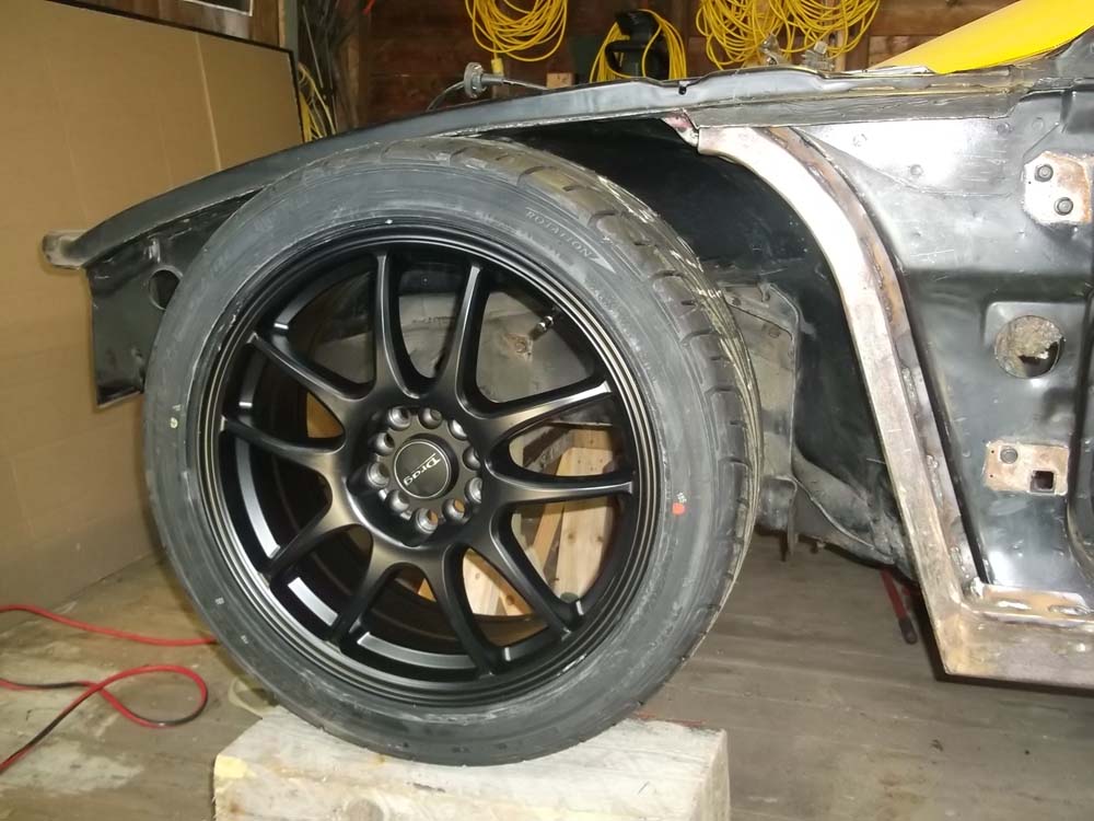
With both frames tacked in place, there was an opportunity to test fit the wheels and make sure there was adequate clearance for everything. The new structure turned out exactly like my 3D drawings said they would :)
|

|
July 4 2013
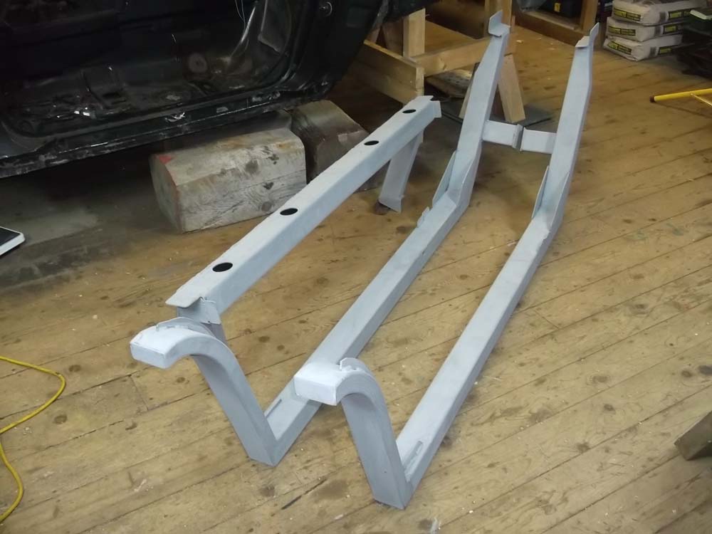
It looks like everything fits perfect. I'll remove them for sandblasting and priming. Like all parts I build, once they are done, I blast me clean and prime them with a suitable welding primer, a product called Nippon Ceramo which we use by the truck load at the ship yard. Here are the parts primed and ready for final installation. You'll notice the other structural part in the photo. I'll discuss that part next in the Roll Over Hoops sub category so please read on.
It looks like everything fits perfect. I'll remove them for sandblasting and priming. Like all parts I build, once they are done, I blast me clean and prime them with a suitable welding primer, a product called Nippon Ceramo which we use by the truck load at the ship yard. Here are the parts primed and ready for final installation. You'll notice the other structural part in the photo. I'll discuss that part next in the Roll Over Hoops sub category so please read on.