rear strut towers
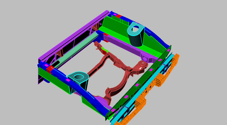
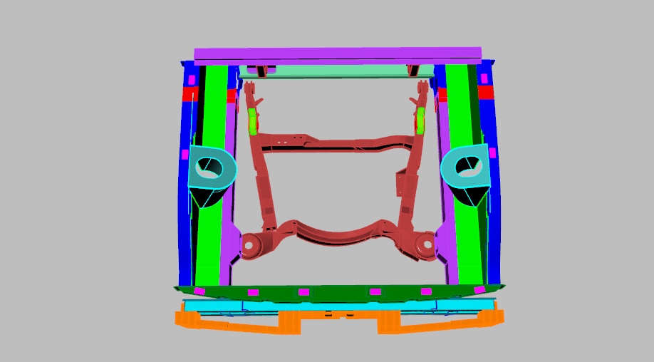
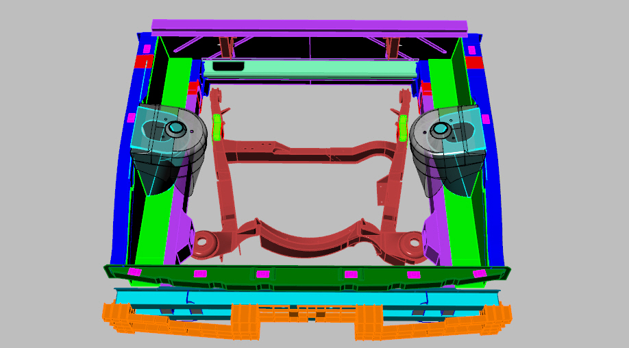
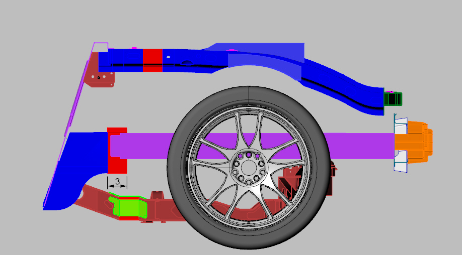
With the rear lower frame rails fabricated and welded in place, the next step is to design and fabricate the new strut towers. The new towers need to accommodate the 4" per side track width increase as well as tie the upper and lower frame rails together to form a structural network surrounding the engine compartment. As well as designing new strut towers, I took this time to design a replacement for the sheet metal that the stock engine compartment had. My goal for this sheathing is to expand on the strut towers structure and tie the entire length of the upper and lower frame rails together. Both the strut towers and the sheathing are to be fabricated from 1/8" plate.
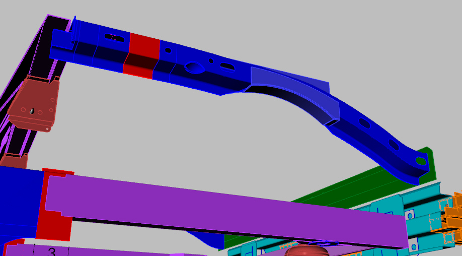
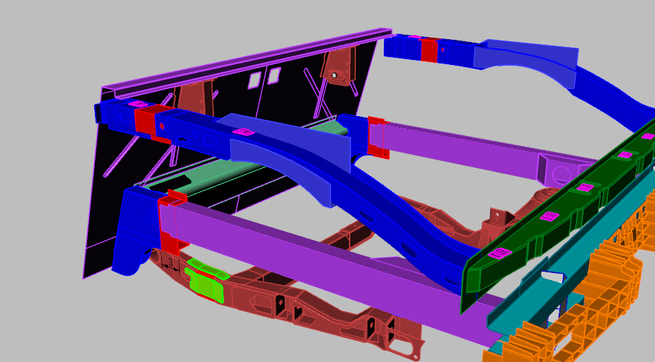
Here is the new design of the strut towers and the sheathing.
Here is the new design of the strut towers and the sheathing.
For reference, here is an overlay of the new strut towers with the stock strut towers ghosted out. It is clear that the wider strut towers will accommodate the wider rear track needed for the 355 body.
Oct 19 2014
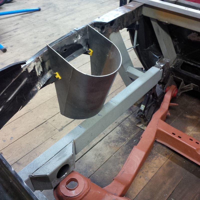
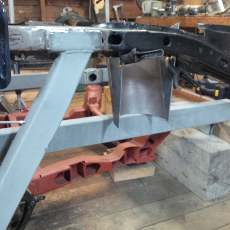
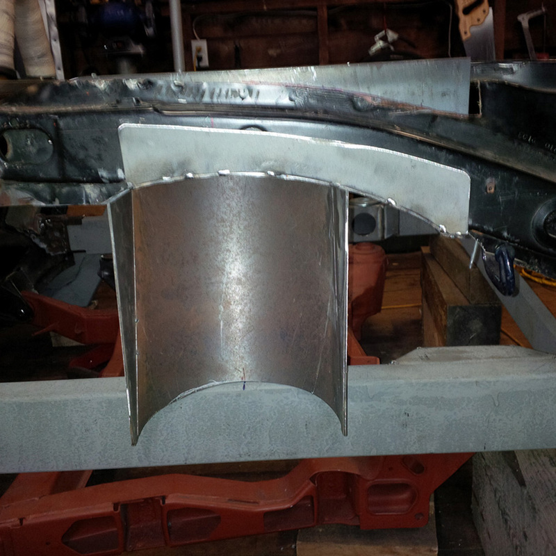
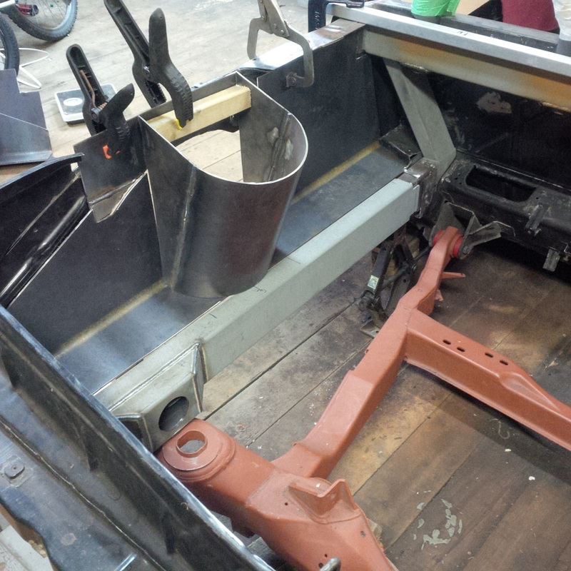
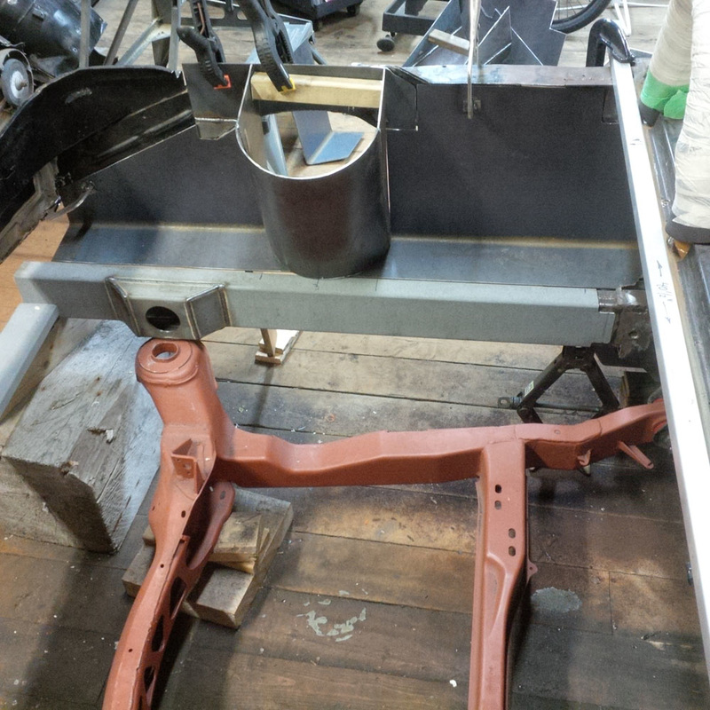
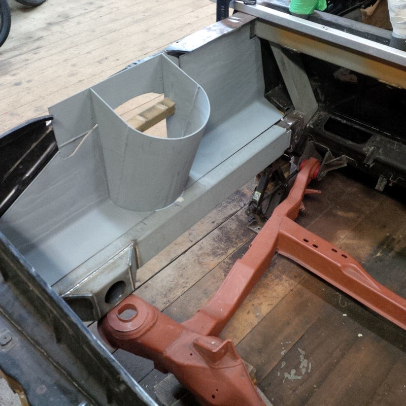
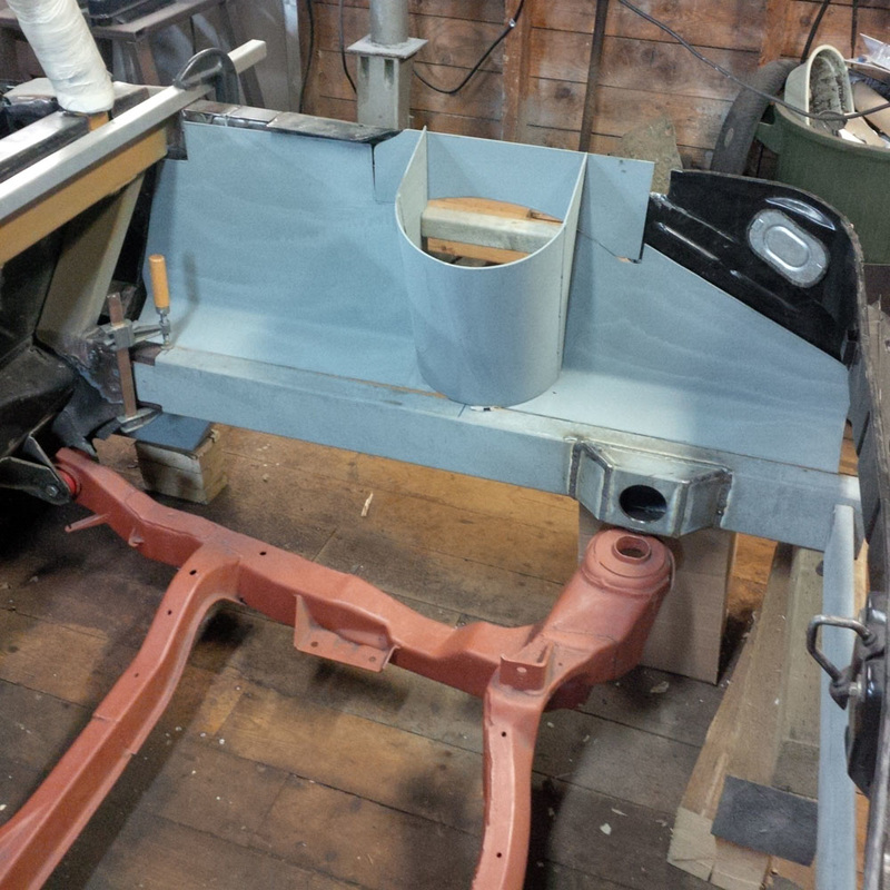
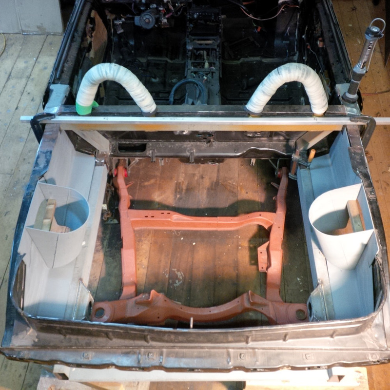
With the new lower frame rails welded in place, the next step is to fabricate the curved shape of the strut towers. These were rolled pieces of 1/8" plate and cut to shape so that they connected the upper and lower frame rails at the correct angle to match the slope of the future coil overs. Here are the towers fitted to confirm the geometry of the structure.
With the new lower frame rails welded in place, the next step is to fabricate the curved shape of the strut towers. These were rolled pieces of 1/8" plate and cut to shape so that they connected the upper and lower frame rails at the correct angle to match the slope of the future coil overs. Here are the towers fitted to confirm the geometry of the structure.
Nov 1 2014
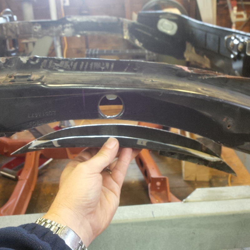
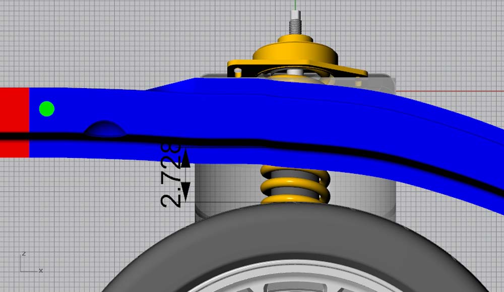
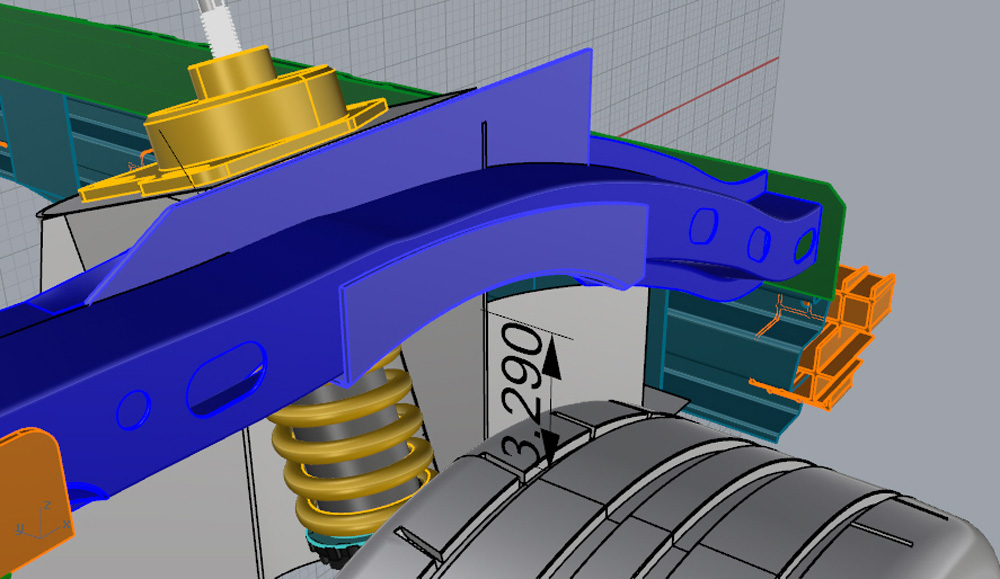
Before proceeding further, it was evident from my 3D model that the inner edge of the upper frame rail was going to be very close to the coil overs. As well, with the available travel of the new suspension design, the rear wheels were going to require a little more clearance in way of the upper frame rails during jounce. I calculate that I will have 3" of travel in jounce so I need atleast this much room to clear the rear tire. Based on my 3D model, I calculated how much of the underside of the upper frame rail would need to be removed. Here is the crescent shaped section I removed from both of the upper frame rails.
Before proceeding further, it was evident from my 3D model that the inner edge of the upper frame rail was going to be very close to the coil overs. As well, with the available travel of the new suspension design, the rear wheels were going to require a little more clearance in way of the upper frame rails during jounce. I calculate that I will have 3" of travel in jounce so I need atleast this much room to clear the rear tire. Based on my 3D model, I calculated how much of the underside of the upper frame rail would need to be removed. Here is the crescent shaped section I removed from both of the upper frame rails.
After this cut was made, it was clear that I now had upper frame rails with a large gaping hole in the underside. I designed a replacement section that would not only seal the frame rails but reinforce the rails and form a solid mounting point for the upper end of the new strut towers.
Here is an image showing the initial clearance of 2-3/4" that I started with and the revised clearance of about 3-1/4" of clearance. All that work for an additional 1/2" of clearance. But I really didn't want to cut out any more that necessary of the upper frame rail.
Dec 26 2014
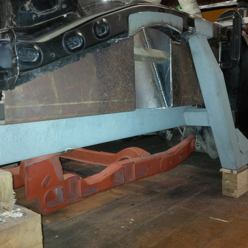
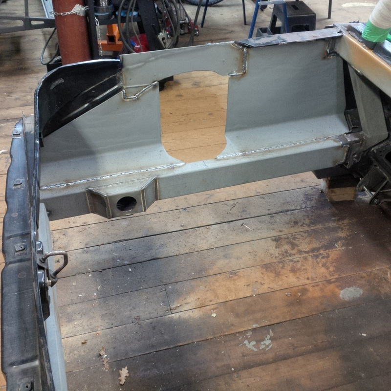
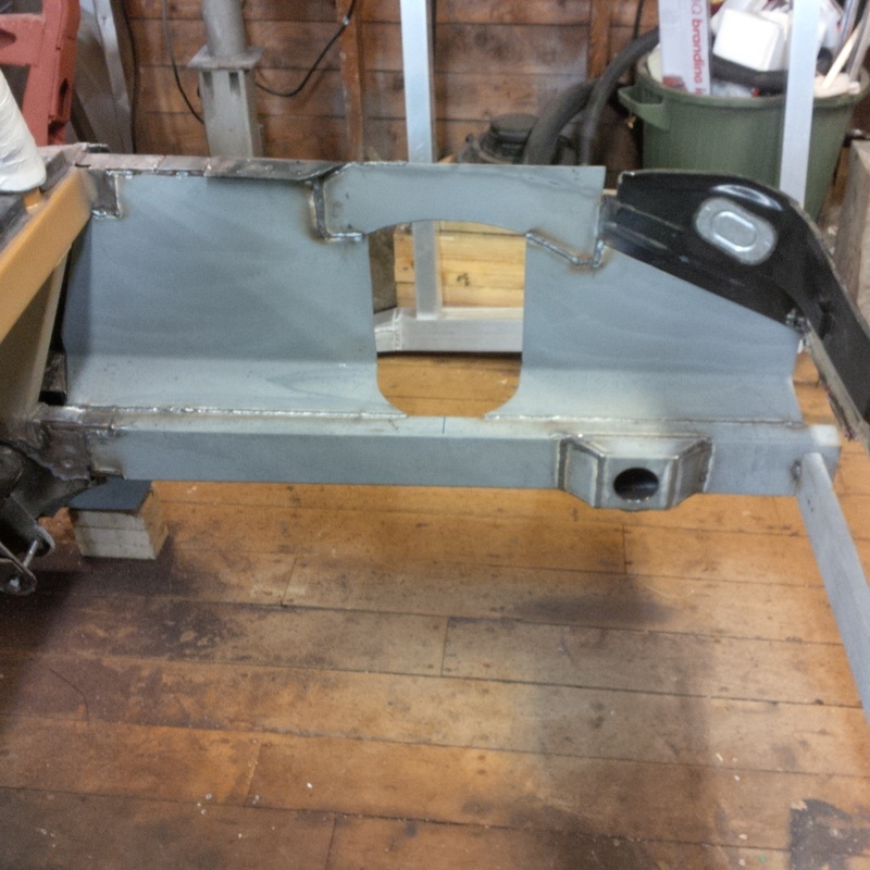
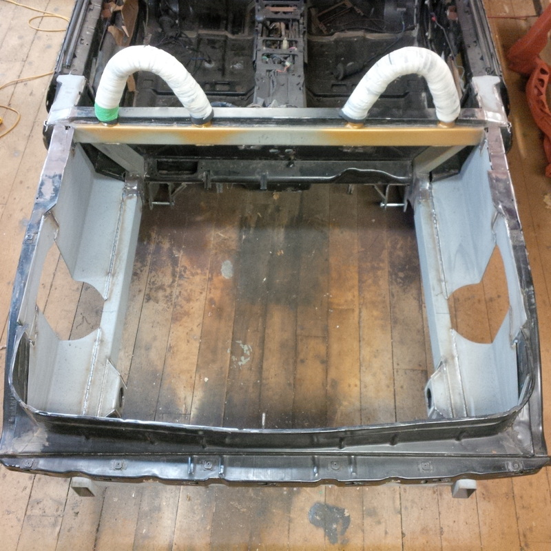
With the upper frame rails notched and the strut towers fabricated, the next step is to install the steel plate sheathing that will not only box in the engine compartment but form a significant structural member by connecting the upper frame rails to their lower counterparts along their entire length. This will create two tall girders extending rearward from the firewall and give the chassis significant strength in all axes. I formed these panels from 1/8" plate by bending them in the brake. Each side is made up of two parts with the strut tower eventually connecting them together. Here are the panels formed and tack welded in place.
With the upper frame rails notched and the strut towers fabricated, the next step is to install the steel plate sheathing that will not only box in the engine compartment but form a significant structural member by connecting the upper frame rails to their lower counterparts along their entire length. This will create two tall girders extending rearward from the firewall and give the chassis significant strength in all axes. I formed these panels from 1/8" plate by bending them in the brake. Each side is made up of two parts with the strut tower eventually connecting them together. Here are the panels formed and tack welded in place.
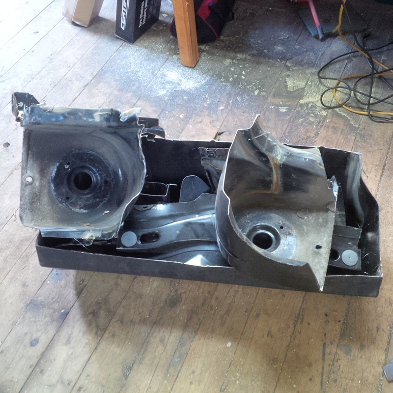
Here is a picture of the new passenger side structure looking from the outside along with a picture of all the sheet metal I have removed from the chassis during this stage of the project.
Dec 29 2014
With all the parts fabricated and test fitted, I removed them all and had them sand blasted and sprayed with welding primer. They were then ready for final assembly and welding to the chassis. I started with the engine bay panels first followed by the strut towers.
With all the parts fabricated and test fitted, I removed them all and had them sand blasted and sprayed with welding primer. They were then ready for final assembly and welding to the chassis. I started with the engine bay panels first followed by the strut towers.
April 20 2015
With the strut tower sides formed and test fitted, the next step is to fit the top plates of the strut towers. I cut these from 1/4" plate and while that is quite thick compared to the stock strut towers, most of the material is removed in the middle to allow the coil over struts to pass though. Here are the plates tacked in place.
With the strut tower sides formed and test fitted, the next step is to fit the top plates of the strut towers. I cut these from 1/4" plate and while that is quite thick compared to the stock strut towers, most of the material is removed in the middle to allow the coil over struts to pass though. Here are the plates tacked in place.
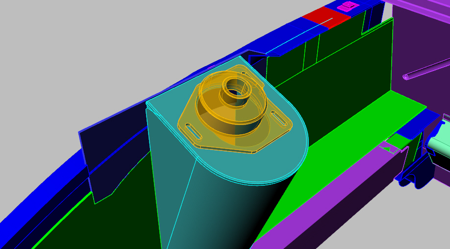
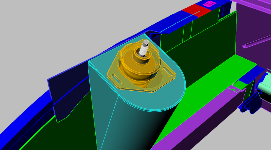
The reason that the holes in the strut towers are oval is so that the strut angle can be adjusted to set the rear wheel camber. I purchased GM camber plates that will accept my coil-overs and when installed will cover the entire hole in the strut tower. Here is what they look like in my drawing.
April 26 2015
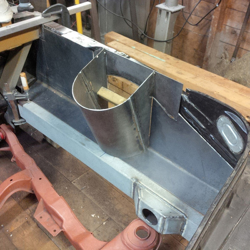
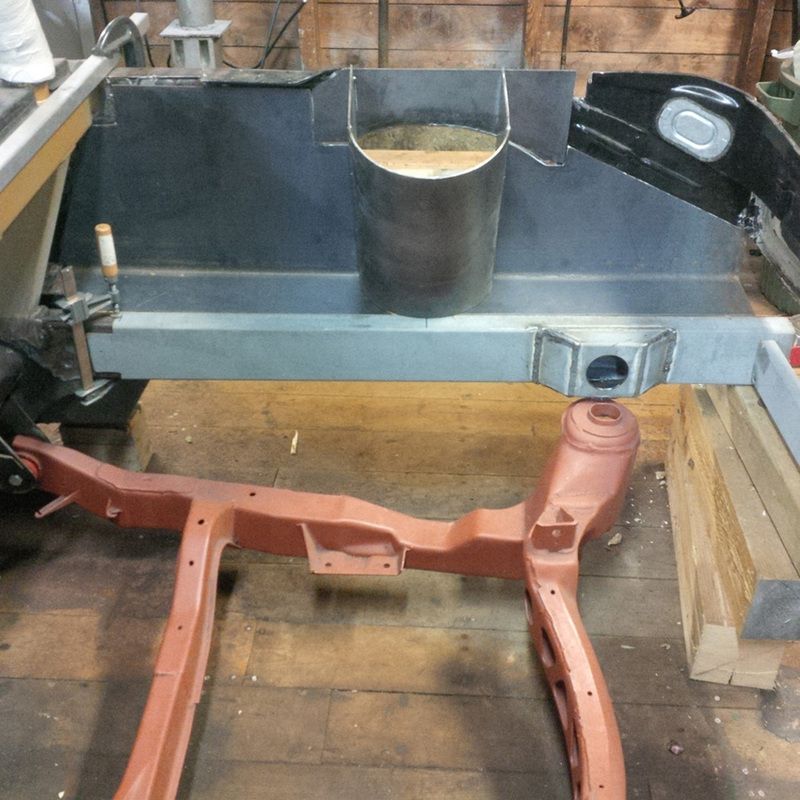
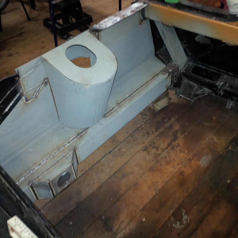
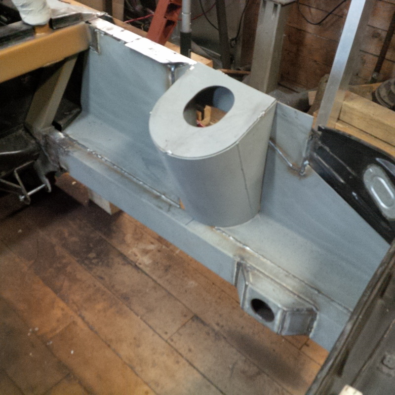
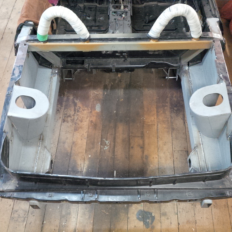
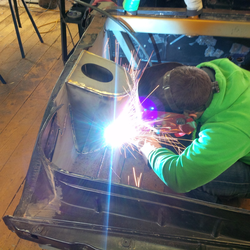
The strut towers are welded in completely now and it significantly stiffened the rear chassis. Alex and I spent the afternoon completing the final fitting and then welding in place. Here are a few pictures with everything welded.
The strut towers are welded in completely now and it significantly stiffened the rear chassis. Alex and I spent the afternoon completing the final fitting and then welding in place. Here are a few pictures with everything welded.
