headers - 180 degree equal length
Oct 30 2017
From the very beginning of this project, when I decided I was doing a longitudinal V8 arrangement, I knew that I also wanted to include a set of custom designed and built 180 degree equal length headers. There was something about the sound of the exhaust and the beauty of a set of well designed and executed headers that I knew would give this project car a touch of exotic appeal. On line, there is no shortage of examples of this style of header on a variety of cars, many of which are very well done. As an example of a true work of art, check out my friend Dave's Faberge equal length 180 degree headers that he designed and built for his transversely mounted Northstar, https://bloozeown.weebly.com/chassis/archives/05-2016
If mine turn out half as nice, I will feel a huge sense of accomplishment.
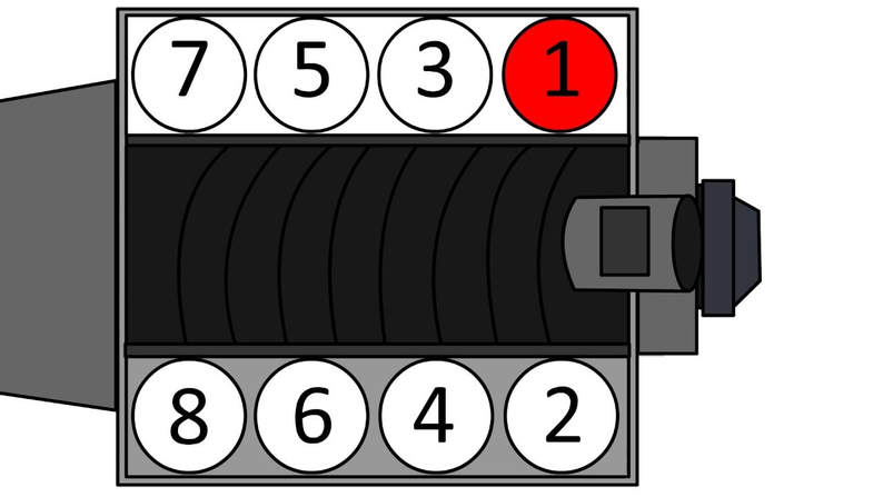
Below, is the cylinder identification with the following firing order for the LS3 - 1, 8, 7, 2, 6, 5, 4, 3 This means that for 180 degree headers, the following cylinder grouping must be maintained for each header:
Left Bank - 1, 7, 6, 4
Right Bank - 8, 2, 5, 3
From this header grouping, you can see that the arrangement will have the typical layout with the center two (2) primaries having to cross from one bank over to the other bank. This is where the magic of the 180 degree headers happens so that no two cylinders fire consecutively into the same header. To truly reap the benefits of this exhaust, its vital that the primary runners are equal length. There are vast amounts of information on line regarding this exhaust arrangement so I will not go too deep into the theory but rather just focus on my solution and resulting header design.
From this point on, I will show my calculations for my header design, primary length and diameter, based on some amazingly simple formula which I have shamelessly borrowed from Dave's website. See link above. There are many different methods for calculating the optimal header characteristics and some methods use much more detailed engine information such as cam and valve geometry. However, the equations I borrowed from Dave are clean, simple and the results make sense. Plus, I know he didn't choose them willy-nilly so I feel confident I will get results that I can be happy with.
Diameter of Header Primary Runners
Primary Cross Sectional Area = peak torque rpm x volume of 1 cylinder
88200
Area = (4500) x (376 cu in) / 8
88200
Area = 2.40 sq in
Primary Runner Diameter = (area * 4 / 3.14)^1/2
Diameter = 1.75 in
This is the interior diameter of the primary runners. For a 16 gauge (0.065") tubing, the outer diameter is 1.88 in.
Length of Header Primary Runners
Primary Runner Length = ((850 x exhaust duration) / Peak Torque rpm) - 3
Length = ((850 x 221) / 4500) - 3
Length = 38.74 in
Diameter of Header Secondary Runners
For street use, a factor of 1.6 is standard
Secondary Runner Diameter = 1.6 x primary diameter
Diameter = 1.6 x 1.75 in
Diameter = .80 in
For a 16 gauge (0.065") tubing, the outer diameter is 2.93 in or nominal 3.00 in
Oct 31 2017
With the diameter of the runners calculated, I have just about everything I need to start designing the headers. I thought the first step would be to find a source for the basic elements I needed so that I could see what was available with regards to material and geometry. No point designing the headers with parts that are not readily available.
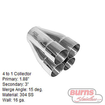
I can across a supplier called Burns Stainless that specializes in exhaust systems and seemed to have a wide selection of parts and material plus all back up with drawings and dimensions. https://www.burnsstainless.com
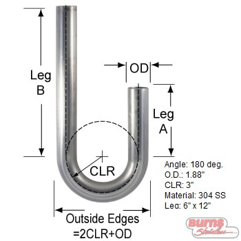
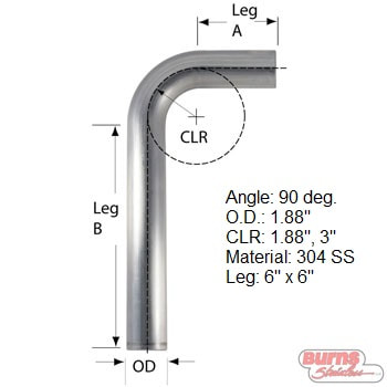
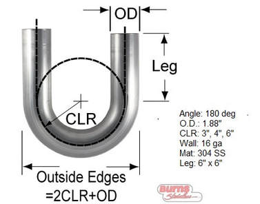
I decided I would build my headers with 304 SS tubing and fittings and use 16 gauge material. From here, I browsed their online catalogue and download the details of parts I would need to design my headers. Here are the various parts, all in the material, diameter and wall thickness I wanted. As you can see, the various parts also come in a selection of radii which will give me a little more flexibility when designing the runners.
Nov 1 2017
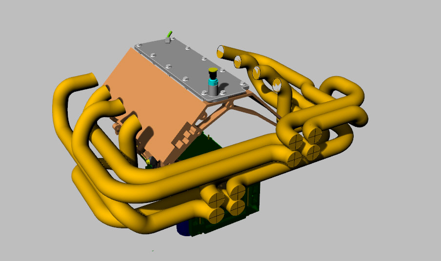
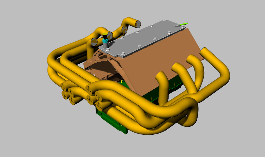
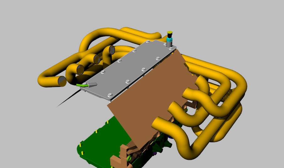
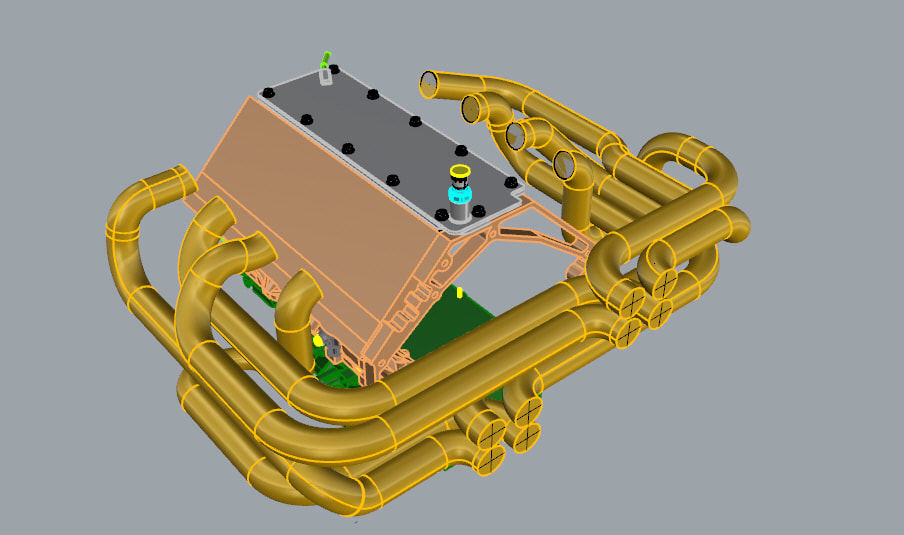
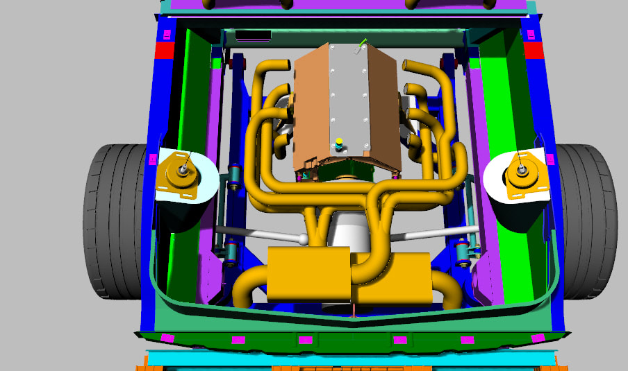
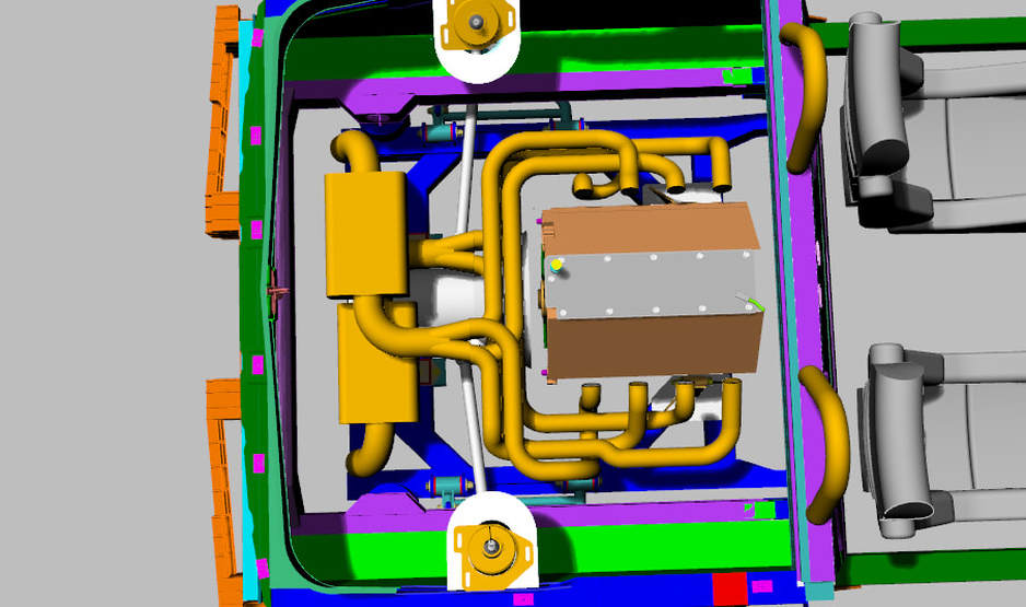
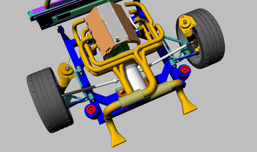
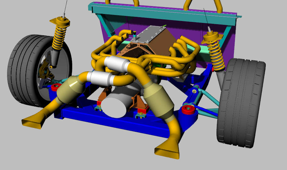
After a few hours on the computer, I managed to layout a basic arrangement for a set of 180 degree headers that fit inside my engine bay. I can see now that the extra 6" chassis stretch I have completed on my 3D model is going to come in handy on my actual chassis. As it looks now, all the primary runners are approximately 39" +/- 1". It will take some fine tuning of the pipework to get them even closer to my desired length of 39". These primary runners have an O.D. of 1-7/8 in (1.88") with an I.D of 1-3/4" as calculated above.
I really need to finish the 3D computer model on my LS3 so you can see the heads. I did locate the exhaust ports pretty accurately though. Here is an image of the runners that is not rendered so that you can see each element that makes up the headers. All the elbows are taken from the various radii available from Burns Stainless shown above.
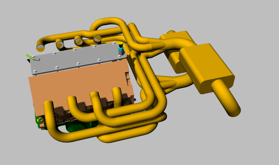
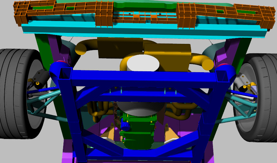
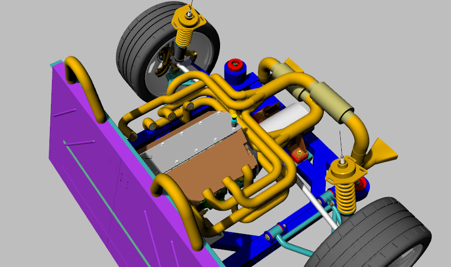
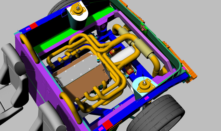
With the basic geometry of the primary runners completed, I decided to add a couple 4 to 1 collectors with a 3" secondary runner and a basic shape muffler. I think they may be a little large as drawn. Also, I would likely turn them up on their side so they hug the rear wall of the engine bay to make a little more room over the transmission. As well, I may have to raise the entire exhaust to clear the transmission more. But for now, the exercise proved to myself that the headers can be built to work. Unfortunately, it's almost 11 pm so I'll post these for now.
Nov 2 2017
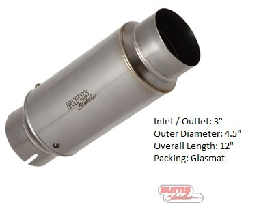
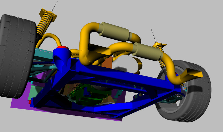
Here is how the setup looks with some sensible mufflers :)
Here is how the setup looks with some sensible mufflers :)
Nov 4 2017
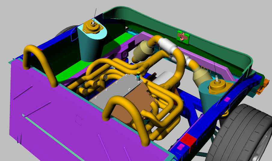
Here is how the setup looks with a set of Magnaflow Race Series mufflers, PN 14159 and a set of Magnaflow Cats, PN 59959. It sure gets crowded back there fast.
Here is how the setup looks with a set of Magnaflow Race Series mufflers, PN 14159 and a set of Magnaflow Cats, PN 59959. It sure gets crowded back there fast.
Nov 5 2017
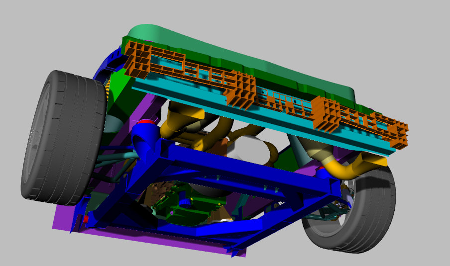
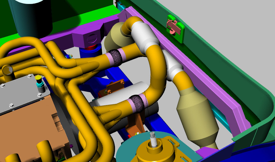
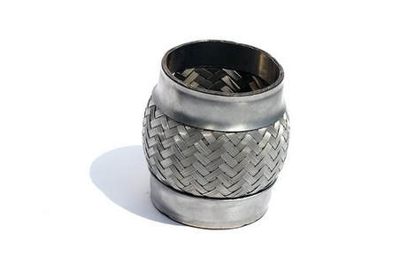
Taking another page from Dave's header design, I have added a set of Yonaka exhaust flexes to my arrangement. They make a 3" diameter x 4" long model, PN YMEFP304-2. The 4" is a little short as it only has about 2" of effective flex length but at the moment, that is all the room I currently have right after my collector on the driver side. The passenger side has room for atleast a 6" model which would allow more flex. Once I have finalized my design, I'll try to squeeze a 6" flex after both collectors. Here is the 4" long flex from Yonaka and how they look on my header design.
Taking another page from Dave's header design, I have added a set of Yonaka exhaust flexes to my arrangement. They make a 3" diameter x 4" long model, PN YMEFP304-2. The 4" is a little short as it only has about 2" of effective flex length but at the moment, that is all the room I currently have right after my collector on the driver side. The passenger side has room for atleast a 6" model which would allow more flex. Once I have finalized my design, I'll try to squeeze a 6" flex after both collectors. Here is the 4" long flex from Yonaka and how they look on my header design.
