LS3 Computer Model
June 6 2017
Like I have done for most of my project, I plan to draw the components I am buying or designing and building and this will include my LS3 crate engine. While the program I am using, Rhino, is sweet to use and powerful to handle very complex forms, you can imagine that measuring engine parts that are either cast or CNC machined can be a very onerous process and then modeling them in 3 dimensions can a very very slow, time consuming and sometimes frustrating process. But I will admit that it is fun to see the complex part slowly take shape. So my plan is to use this page of my website to document the development of the engine and possibly the gearbox. I will show various views of the parts to emphasize unique and complex features. I probably won't list all new posts in the Updates folder as they really aren't advancements in my project. So pop in from time to time to see if I have added to the computer model, if you find it of interest. You'll likely see the developed engine model show up in other folders anyway as supporting documentation.
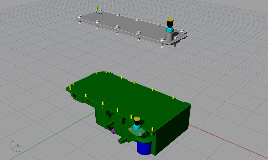
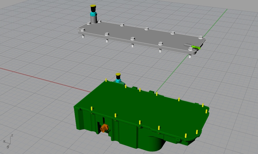
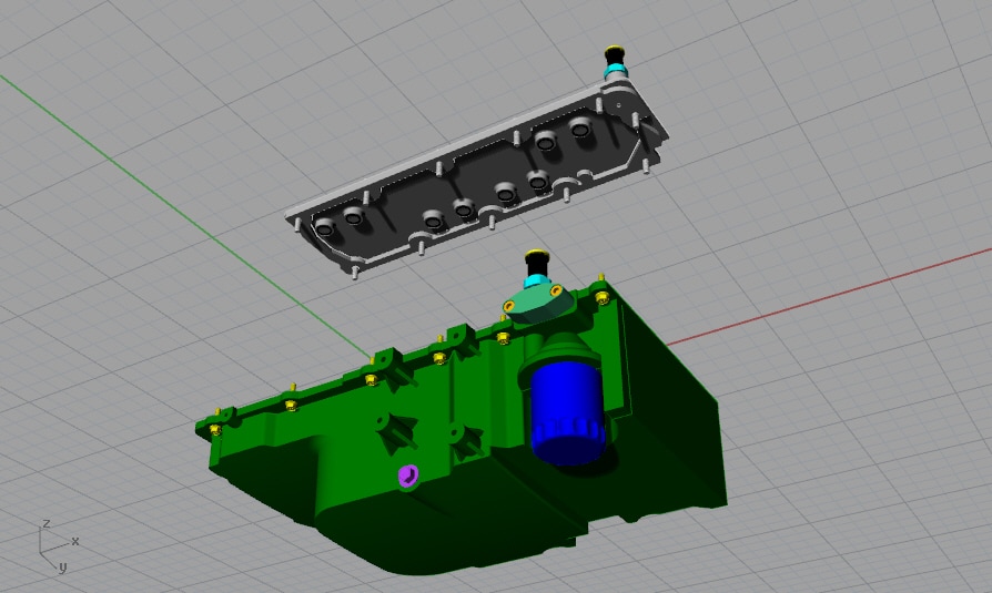
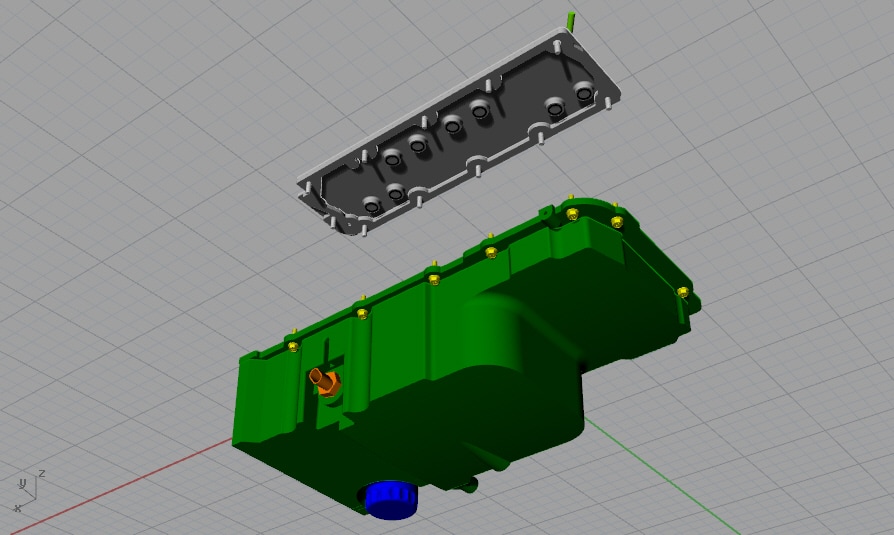
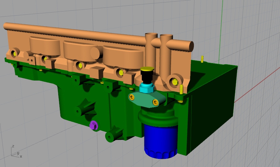
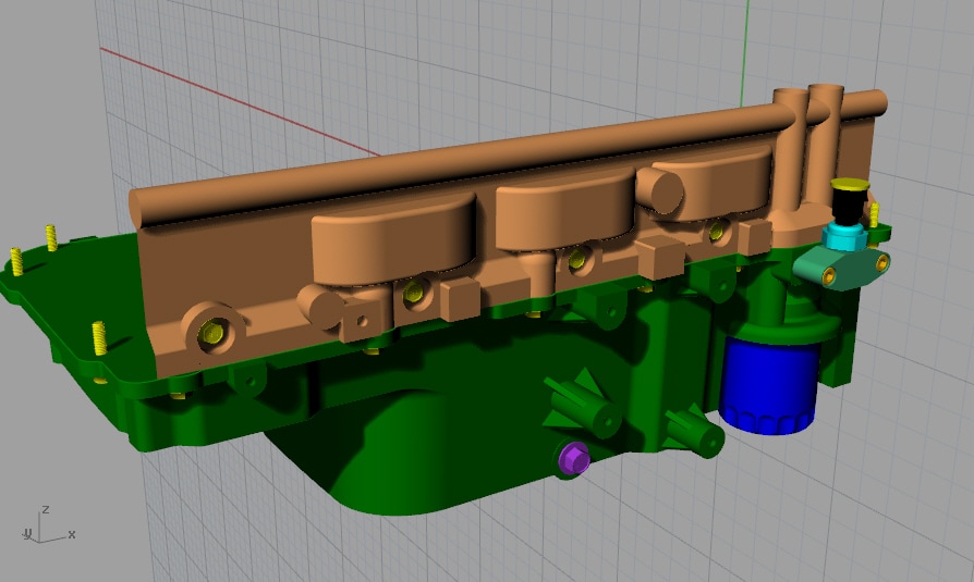
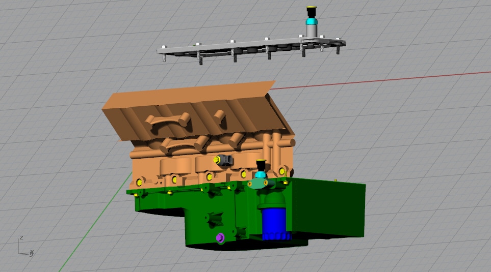
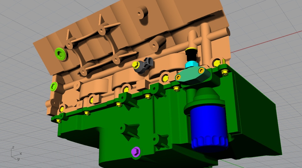
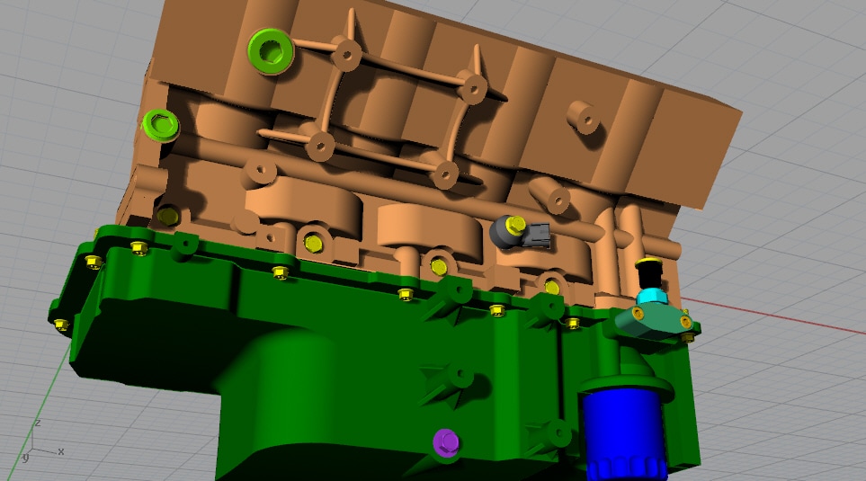
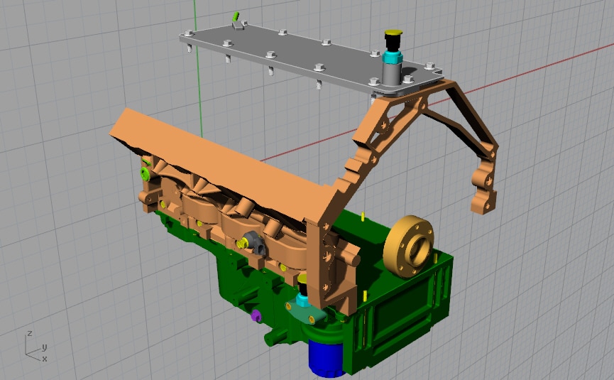
So to kick off this page, here is the status of the LS3 model as of today. I usually try to draw parts as I have them removed from the engine, so since I have modified the rocker valley cover already and as well drawn the oil pan as part of the engine cradle development, here they are in relative position to one another. You'll notice that I am drawing the parts as they are in stock form so as not to confuse anyone, as well as to include my various modifications (ie: oil pressure sending unit appears in both locations.
July 2 2017
With the development of the engine model slowly progressing, I have reached a point where I have to map out the bell housing. While the majority of the engine model requires modest accuracy and detail precision, the bell housing is going to have to be accurate to 3 decimal places. The reason for this is that I am going to fabricate a custom adapter plate to bolt together the LS3 and the Audi 01e gearbox. The reason I am considering a custom adapter plate as to opposed to one off the shelf from a supplier is that I may do a custom flywheel and clutch set up, similar to my friend Dave, aka Bloozberry. This means I may need an adapter plate with a custom thickness. As well, I have a design in the deep reaches of my brain for a very custom belt drive set up to correct for my drive line offset. I think I mentioned this a long time ago in my old build thread on Pennocks. The idea is still in the early design stage but I'll post more on this as it develops. The connection to the adapter plate is that I may need to use extensions on the adapter plate to support one end of the belt drive system. More to come on this topic.
With the development of the engine model slowly progressing, I have reached a point where I have to map out the bell housing. While the majority of the engine model requires modest accuracy and detail precision, the bell housing is going to have to be accurate to 3 decimal places. The reason for this is that I am going to fabricate a custom adapter plate to bolt together the LS3 and the Audi 01e gearbox. The reason I am considering a custom adapter plate as to opposed to one off the shelf from a supplier is that I may do a custom flywheel and clutch set up, similar to my friend Dave, aka Bloozberry. This means I may need an adapter plate with a custom thickness. As well, I have a design in the deep reaches of my brain for a very custom belt drive set up to correct for my drive line offset. I think I mentioned this a long time ago in my old build thread on Pennocks. The idea is still in the early design stage but I'll post more on this as it develops. The connection to the adapter plate is that I may need to use extensions on the adapter plate to support one end of the belt drive system. More to come on this topic.
|
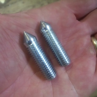
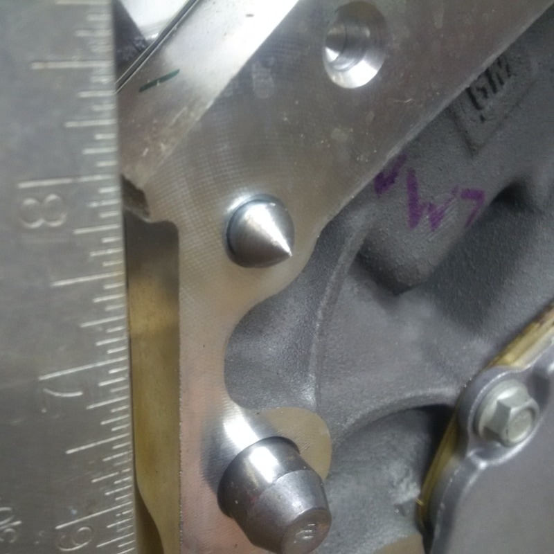
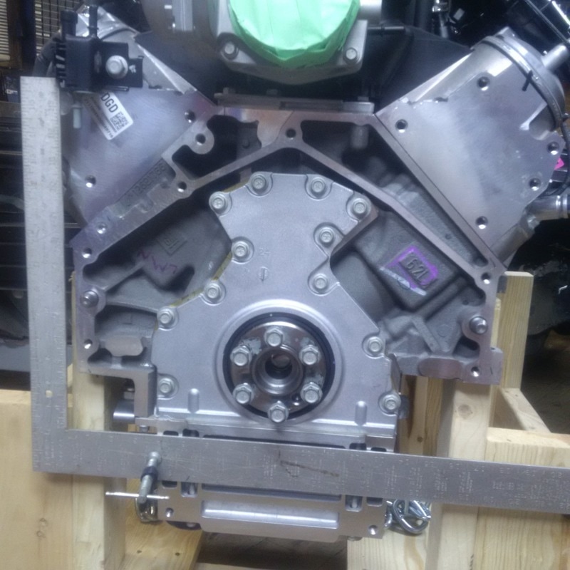
To assist in mapping the bell housing, I had a couple M10 x 1.5 bolts machined into dead centers so that I could screw them into the bell housing threaded holes and use them to locate the holes in reference to a datum that I secured to the block. Then it was just a matter of locating all the bolt holes, locating pins and crank flange on the bell housing surface by measuring in the X, Y and Z axes with a digital vernier.
|
