control arms
Jan 31 2015
With all the changes I have been making to the rear suspension, it was only natural that I would replace the stock rear control arm with a custom designed and built tubular control arm. This way, I could have more freedom with regards to control arm geometry.
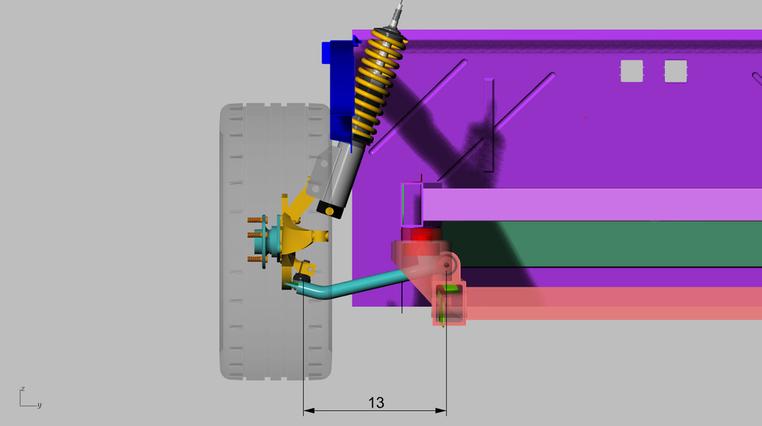
The starting point for my design was the geometry of the wheels. I think it was a lot easier to select the wheels that I wanted without worrying about their offset matching the suspension requirements. Having a clear idea about where the wheels would need to sit with regard to the bodywork meant that I could position them where I wanted and then work out the required geometry of the control arms to connect the wheels to the chassis (engine cradle). With the engine cradle designed and built, it was a simple matter to calculate the required length of the control arm. Like the length, the height of the control arm was based on the diameter of the wheels, ties , ball joint and spindle on the outboard end and the height of the engine cradle on the inboard end.
Here is a drawing showing the control arm length required with the wheels, spindle and engine cradle shown for reference.
With all the changes I have been making to the rear suspension, it was only natural that I would replace the stock rear control arm with a custom designed and built tubular control arm. This way, I could have more freedom with regards to control arm geometry.
The starting point for my design was the geometry of the wheels. I think it was a lot easier to select the wheels that I wanted without worrying about their offset matching the suspension requirements. Having a clear idea about where the wheels would need to sit with regard to the bodywork meant that I could position them where I wanted and then work out the required geometry of the control arms to connect the wheels to the chassis (engine cradle). With the engine cradle designed and built, it was a simple matter to calculate the required length of the control arm. Like the length, the height of the control arm was based on the diameter of the wheels, ties , ball joint and spindle on the outboard end and the height of the engine cradle on the inboard end.
Here is a drawing showing the control arm length required with the wheels, spindle and engine cradle shown for reference.
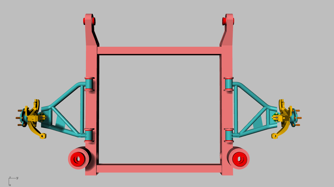
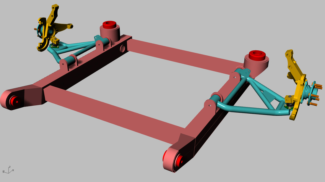
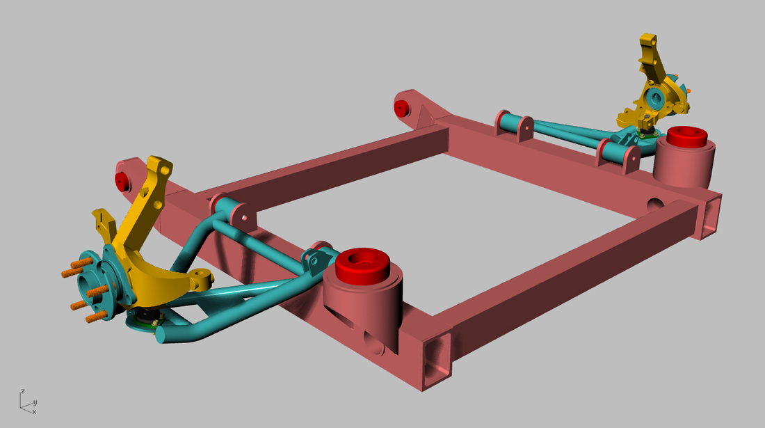
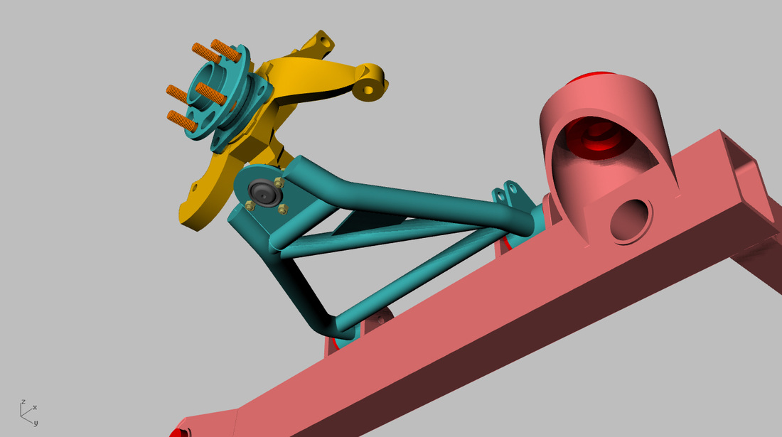
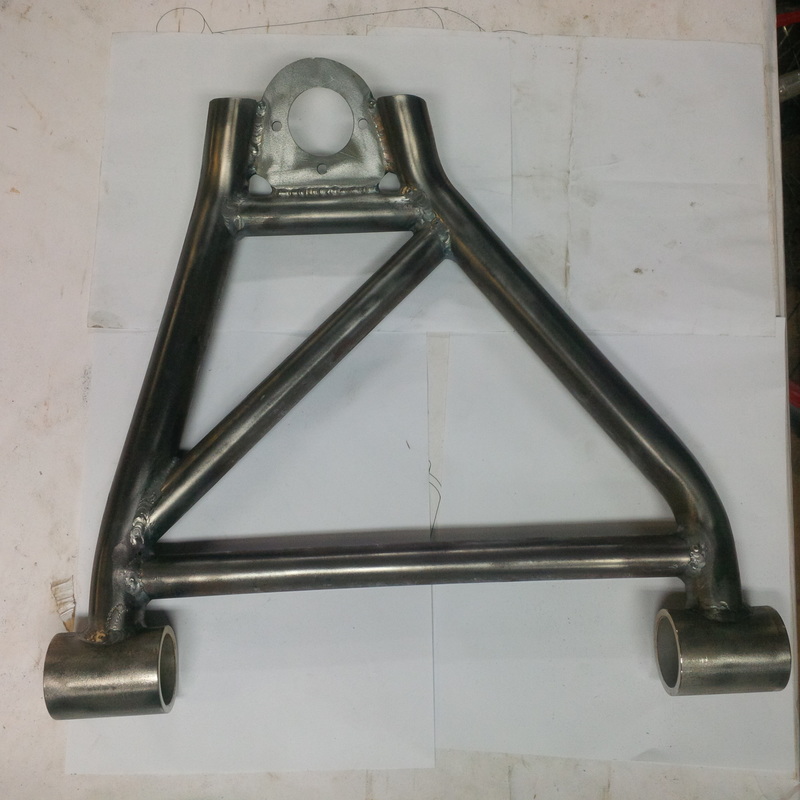
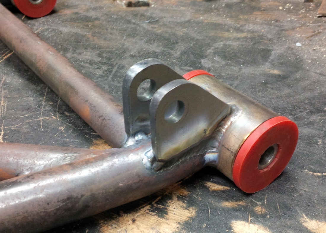
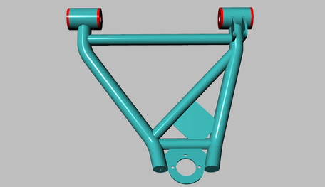
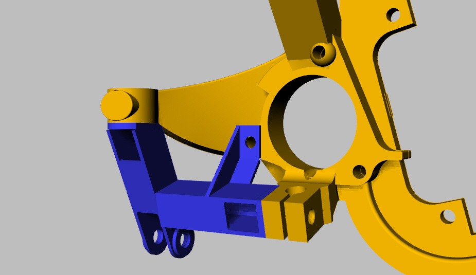
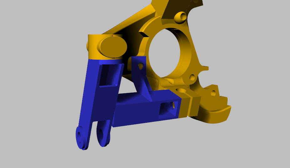
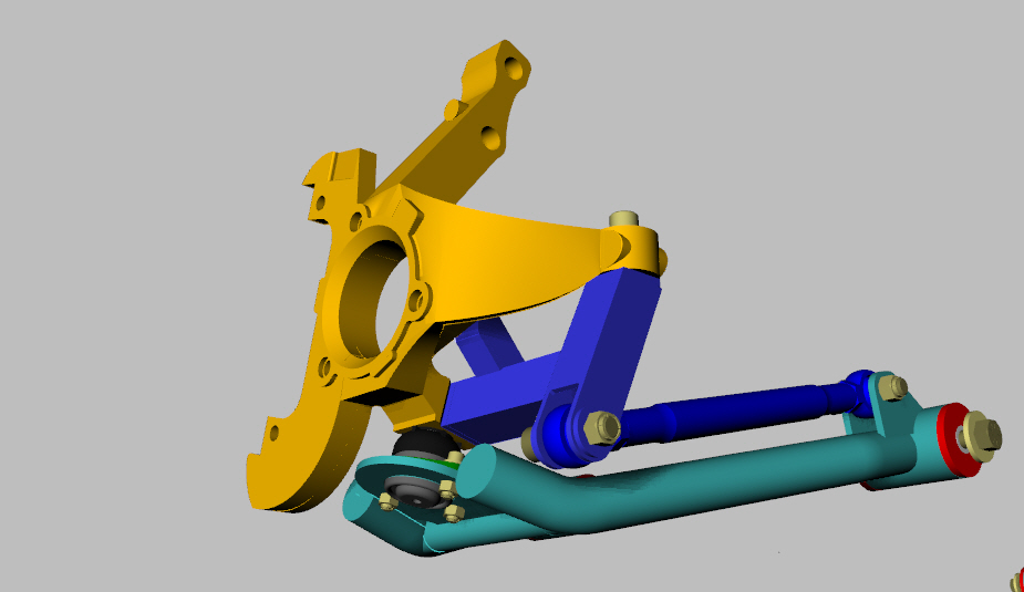
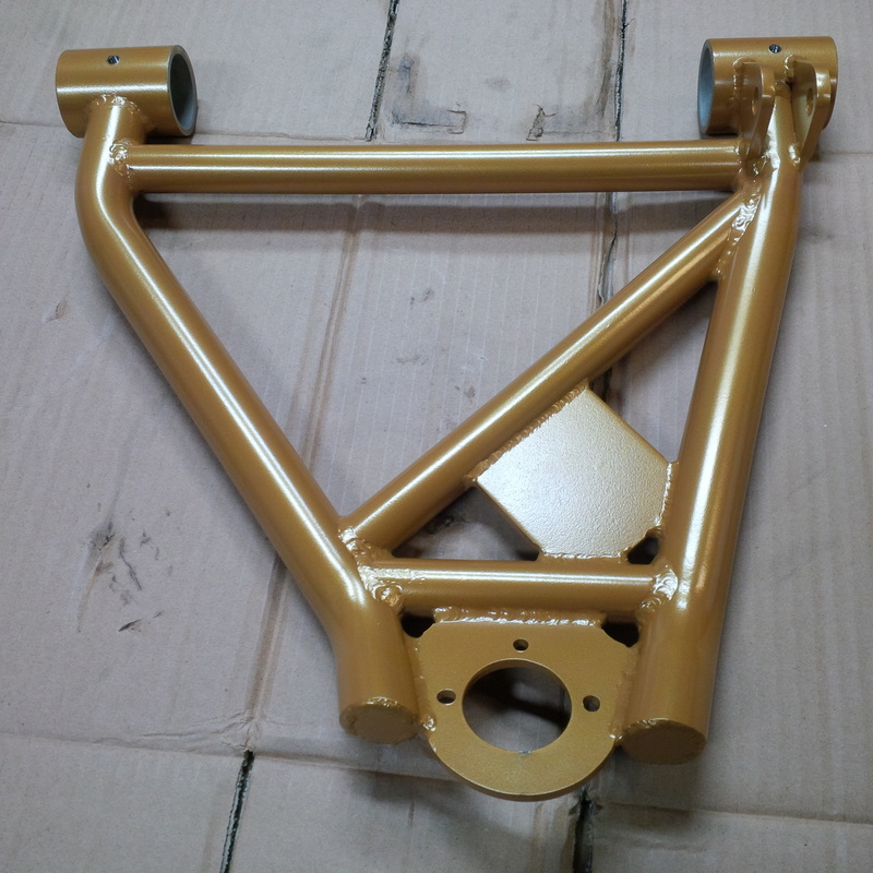
Here is the final design of my rear control arm. The main bushing sleeves are 2" dia. seamless SS tubing, the main control arm rails are 1 1/4" dia. seamless tubing and the cross bracing is 1" dia. seamless tubing and the ball joint plate is 3/16" plate. I also added an intermediate plate for a future sway bar linkage mount as well as a mount for the bump steer linkage which I will discuss further on.

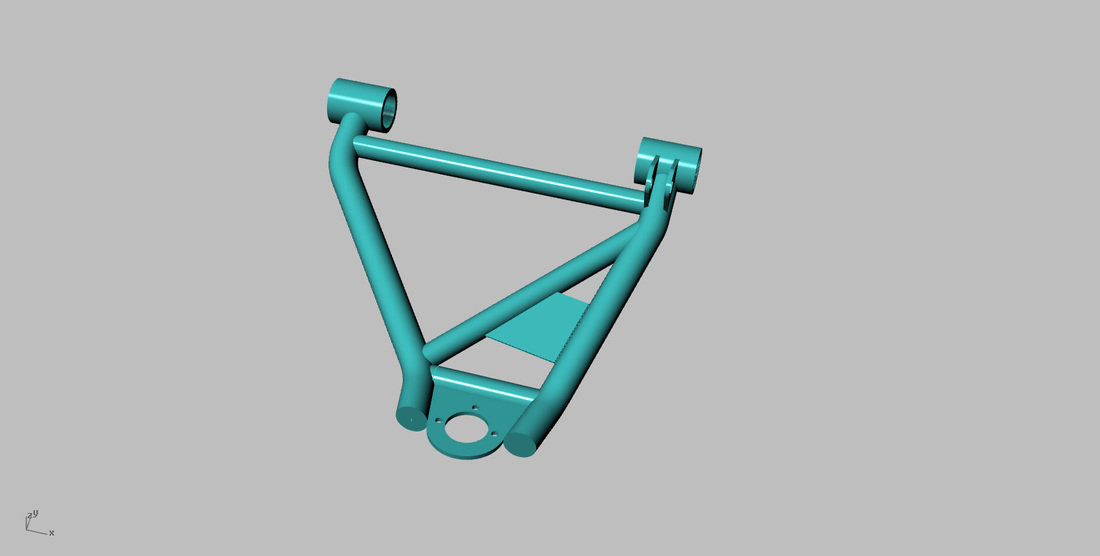
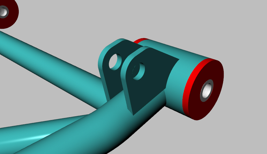
Here are a few images from the 3D model showing the new control arms mounted with poly bushings on the cradle with the ball joint and spindle in place.
|
|
April 20 2015
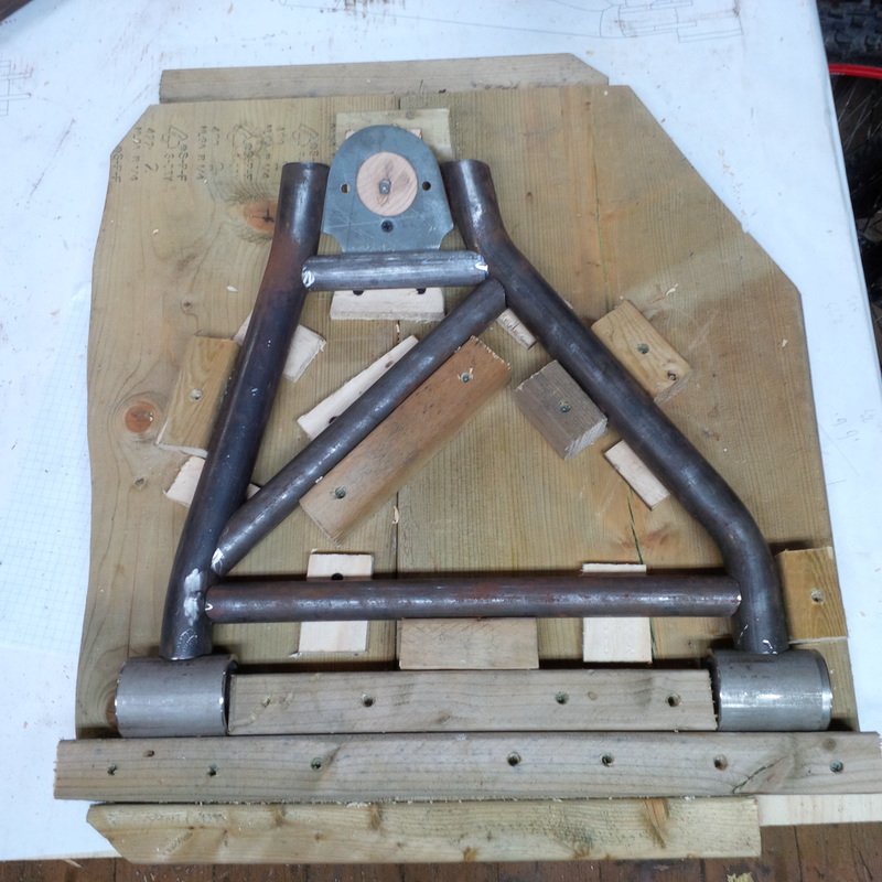
Here is the drivers side control arm mocked up in the jig and ready for welding.
Here is the drivers side control arm mocked up in the jig and ready for welding.
May 1 2015
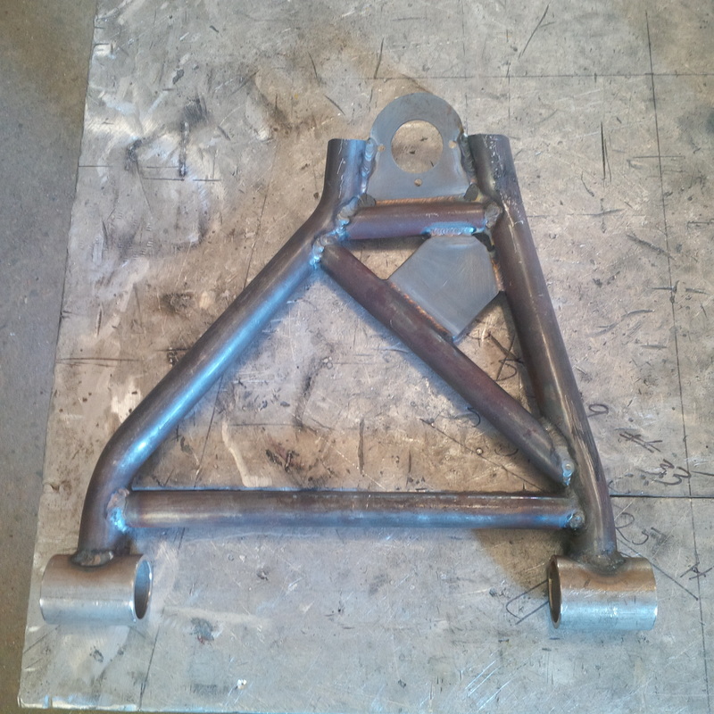
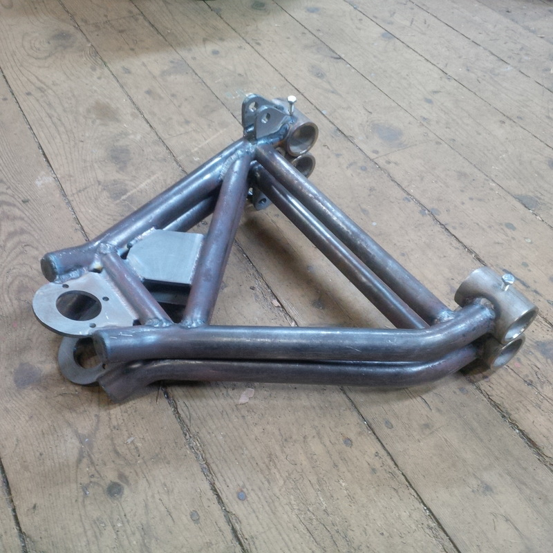
This is the driver side control arm tig welded. I still need to add the two small gussets for the bump steer arm and the mounting plate for the sway bar attachment.
This is the driver side control arm tig welded. I still need to add the two small gussets for the bump steer arm and the mounting plate for the sway bar attachment.
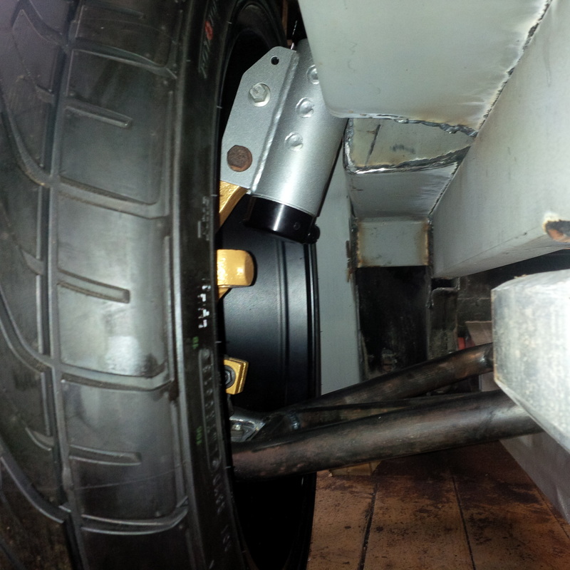
Here are a few pictures of the driver side suspension mocked up with the control arm, spindle, brake rotor, ball joint, strut and camber plate. Its a tight fit that's for sure but it looks like its all going to fit. I left the strut spring off as there is not enough weight in the bare chassis to compress it.
|

|
|

|
Nov 11 2015
With the driver side rear control arm fabricated, the next step was to add the connection point for the bump steer tie rod and the mounting plate for a future sway bar linkage. Here is the design and the final control arm with all components welded.
With the driver side rear control arm fabricated, the next step was to add the connection point for the bump steer tie rod and the mounting plate for a future sway bar linkage. Here is the design and the final control arm with all components welded.
|
|
I altered the shape of the sway bar linkage mounting plate so that it would act as a strengthening gusset for the control arm as well by tying three structural members together.
|

|
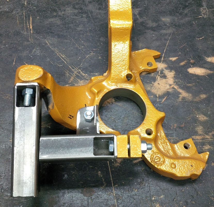
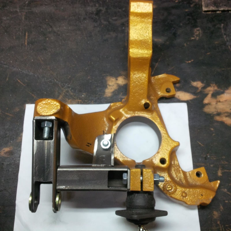
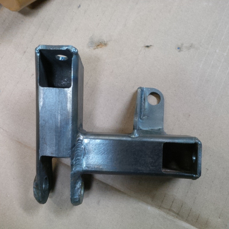
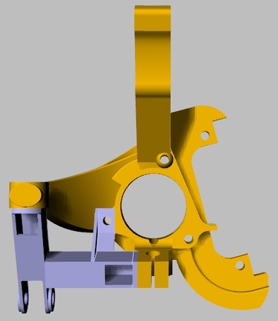
With the control arm complete, the next step is to fabricate the bump steer extension for the spindle. My original design had the extension fabricated from 1-1/4" x 1-1/4" channel. However, I decided to fabricate the assembly using 1-1/4" x 1-1/4" square HSS to add extra strength. This required me to add access opening to get at the nuts that will fasten the assembly to the spindle. Here is the original design and also the initial stages of fabrication showing the square hollow structure being used.

|
|
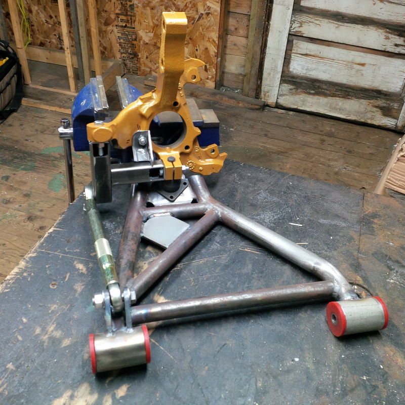
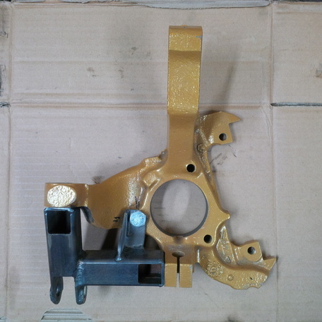
Here is the rear driver side control arm and spindle partially fabricated and assembled with the bump steel linkage.
|
|
Nov 26 2015
With the drivers side rear lower control arm complete, it was time to tackle the passenger side. As they are mirror images of each other, the first task was to reverse the jig. Once the jig was disassembled, I laid out a full size drawing of the passenger side control arm on the jig platform and then built the jig components directly on top of the paper drawing. This ensured that the dimensions would be correct. I continually confirmed dimensions of each component of the jig with the driver side control arm, just to reassure myself I was getting it right. Then the process began of cutting the various tubes and notching them to get a suitable fit with each other. I won't lie, I went through alot of tubing during this process. Luckily, I had done a pretty good job of bending the main rail tubes at work so those angles were a good starting point.
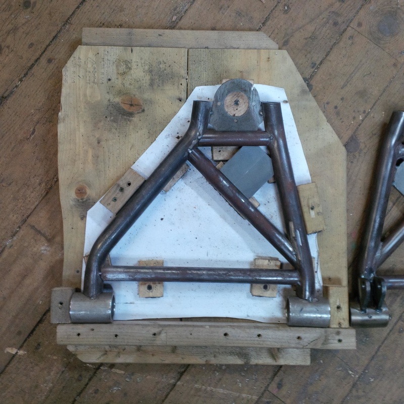
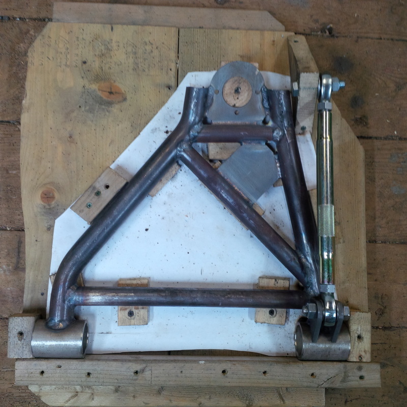
Here is the passenger side lower rear control arm jigged and tacked together. The second picture shows the two control arms side by side. I'll take the whole arm mounted in the jig and get it welded by a certified welder at work. Again, a little piece of mind for when I am taking the country back roads a little too fast. :)
With the drivers side rear lower control arm complete, it was time to tackle the passenger side. As they are mirror images of each other, the first task was to reverse the jig. Once the jig was disassembled, I laid out a full size drawing of the passenger side control arm on the jig platform and then built the jig components directly on top of the paper drawing. This ensured that the dimensions would be correct. I continually confirmed dimensions of each component of the jig with the driver side control arm, just to reassure myself I was getting it right. Then the process began of cutting the various tubes and notching them to get a suitable fit with each other. I won't lie, I went through alot of tubing during this process. Luckily, I had done a pretty good job of bending the main rail tubes at work so those angles were a good starting point.
Here is the passenger side lower rear control arm jigged and tacked together. The second picture shows the two control arms side by side. I'll take the whole arm mounted in the jig and get it welded by a certified welder at work. Again, a little piece of mind for when I am taking the country back roads a little too fast. :)
|

|
Once the welding is complete, I'll add the two lugs for the bump steer linkage. Then drill and tap the bushings for grease fittings. Finally, I'll have the parts sand blasted and sent for powdercoating.
Nov 29 2015
With the passenger side control arm off for welding, I returned my focus to the bump steer extensions which I had already started for the driver side. I think I should have made a sub section under my rear suspension heading just for these bump steer parts as they are quite important. I may rearrange this post once it's complete.
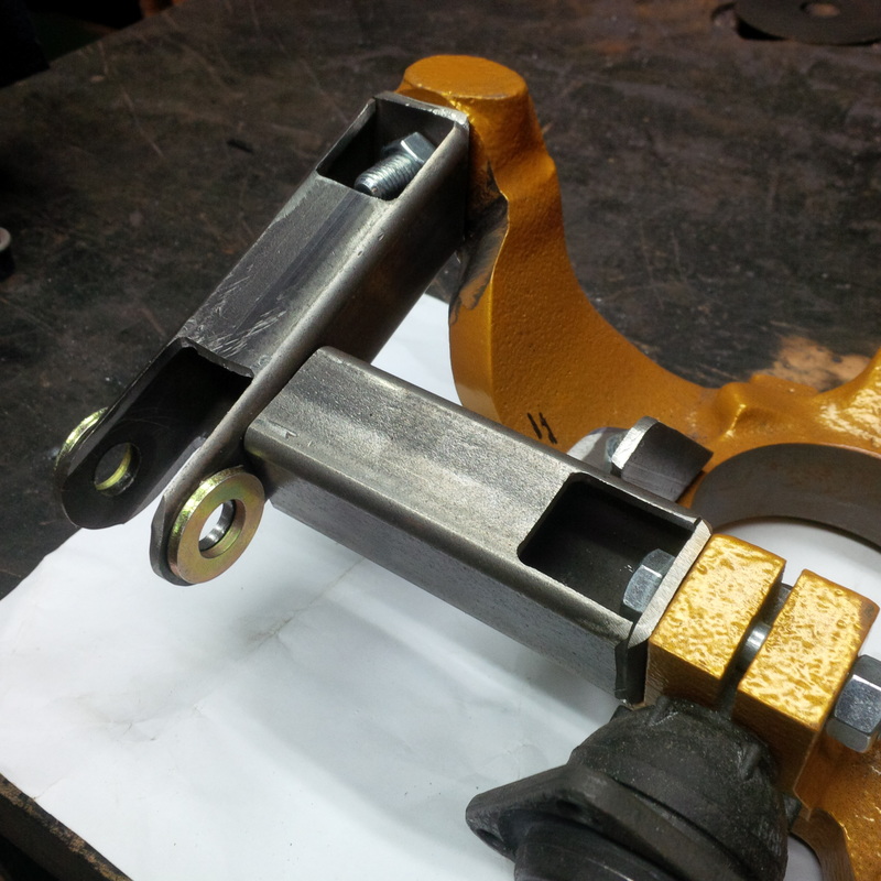
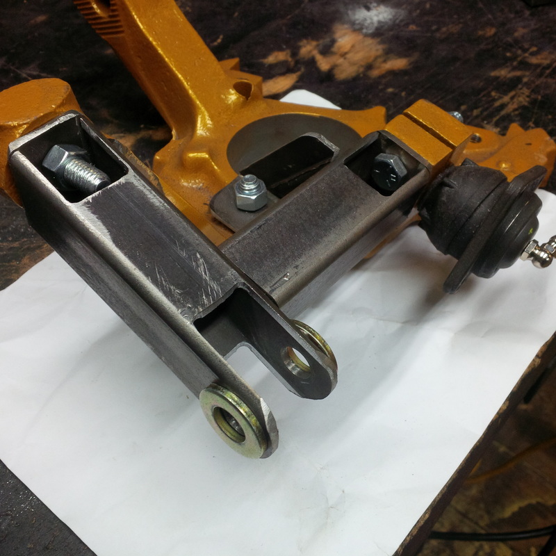
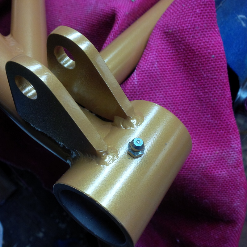
As I mentioned above, I made the bump steer extensions from 1-1/4" x 1-1/4" x 1/8" square tubing. I just felt this might add additional strength to the structure. So here is the drivers side completed and ready for welding. I added a thick washer to each side of the lower linkage end connection just to add a little meat where the loads will be highest. My original design ( seen above) had a gusset between the vertical member and the horizontal member. I am not convinced I need it although I may add it after the initial parts are welded together.
With the passenger side control arm off for welding, I returned my focus to the bump steer extensions which I had already started for the driver side. I think I should have made a sub section under my rear suspension heading just for these bump steer parts as they are quite important. I may rearrange this post once it's complete.
As I mentioned above, I made the bump steer extensions from 1-1/4" x 1-1/4" x 1/8" square tubing. I just felt this might add additional strength to the structure. So here is the drivers side completed and ready for welding. I added a thick washer to each side of the lower linkage end connection just to add a little meat where the loads will be highest. My original design ( seen above) had a gusset between the vertical member and the horizontal member. I am not convinced I need it although I may add it after the initial parts are welded together.
|
|
|
|

|

|
|
|
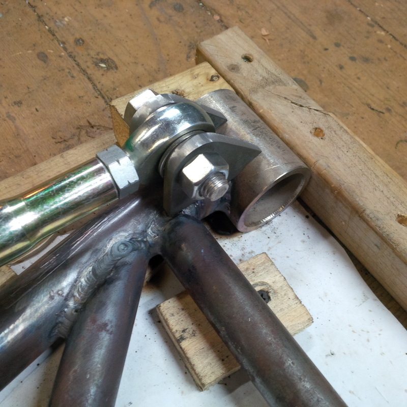
My bump steer tie rode is approximately 3/8" too long as shown so once everything is assembled I will remove 3/8" from each of the threaded ends, giving me the right length plus a little room for final adjustment of the length during wheel alignment. That is so far in the future, its almost hard to imagine ha-ha-ha.
|
Dec 1 2015
Here is the passenger side rear lower control arm welded and ready to be fitted with the bump steer linkage lugs and then drill and tap the bushing for grease fittings before going to the powdercoater for blasting and spraying. |
|
Dec 3 2015
The bump steer linkage lugs are fabricated and in place ready for welding to the passenger rear control arm.
The bump steer linkage lugs are fabricated and in place ready for welding to the passenger rear control arm.
|
|
Dec 9 2015
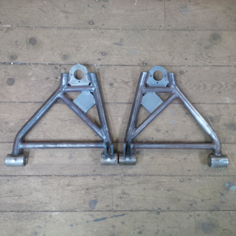
The passenger side control arm is fully welded, drilled and tapped for grease fittings. Off for sand blasting and powder coating this weekend. Here are a few images of the two control arms together to show their geometry and symmetry.
The passenger side control arm is fully welded, drilled and tapped for grease fittings. Off for sand blasting and powder coating this weekend. Here are a few images of the two control arms together to show their geometry and symmetry.
|

|
Dec 13 2015
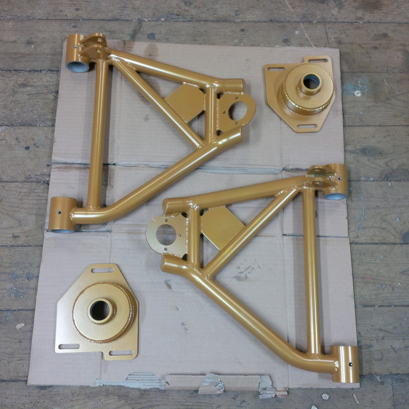
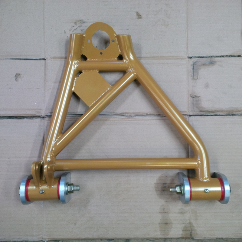
My parts just came back from powder coating tonight. Here are the two control arms and the two strut tower camber plates all done in Gold Nugget 365. They should look pretty good against the black engine bay and rear chassis structure.
My parts just came back from powder coating tonight. Here are the two control arms and the two strut tower camber plates all done in Gold Nugget 365. They should look pretty good against the black engine bay and rear chassis structure.
Dec 14 2015
The driver side bump steer extension was welded today and it turned out great. Time to build one for the passenger side now. For a small part, there is alot of work required to make those square holes and get everything aligned. But I think the improvement to the rear suspension geometry will be well worth the effort.
The driver side bump steer extension was welded today and it turned out great. Time to build one for the passenger side now. For a small part, there is alot of work required to make those square holes and get everything aligned. But I think the improvement to the rear suspension geometry will be well worth the effort.
|
|
Dec 19 2015
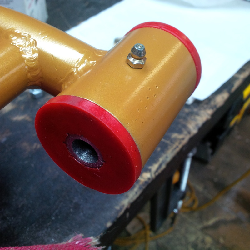
With the control arms finished and powder coated, it is time to install the grease fittings and poly bushings. The grease fittings are 1/4" - 28 straight style. I had drilled and tapped a hole on the top of each control arm bushing sleeve prior to powder coating to take the grease fittings. I doubt the poly bushings will need much greasing attention once installed but its easy to install the fittings now for future use. I have an awesome guy doing my powder coating and he really takes the time to mask the parts with high temp tape to give nice clean edges.
With the control arms finished and powder coated, it is time to install the grease fittings and poly bushings. The grease fittings are 1/4" - 28 straight style. I had drilled and tapped a hole on the top of each control arm bushing sleeve prior to powder coating to take the grease fittings. I doubt the poly bushings will need much greasing attention once installed but its easy to install the fittings now for future use. I have an awesome guy doing my powder coating and he really takes the time to mask the parts with high temp tape to give nice clean edges.
When I was designing my control arms, I wanted the bushing sleeves to be a little longer than the stock control arms. Since the stock poly bushing would then be too short, I decided to purchase a couple sets of poly bushings and use four per control arm. This would allow me to insert one bushing in from each side of the bushing sleeve. To account for the fact that my sleeves were not twice as long as stock sleeves, I shortened each bushing. I also did away with the steel inner bushing sleeves that were now too short and had new bushing sleeves made from 316 SS bar stock and bored to take the 1/2" dia. control arm bolts.
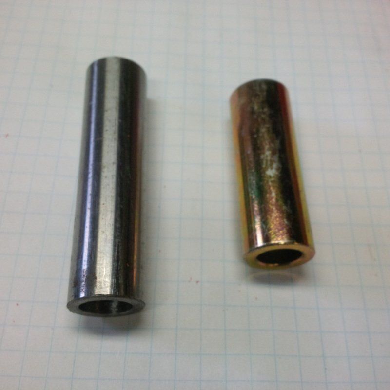
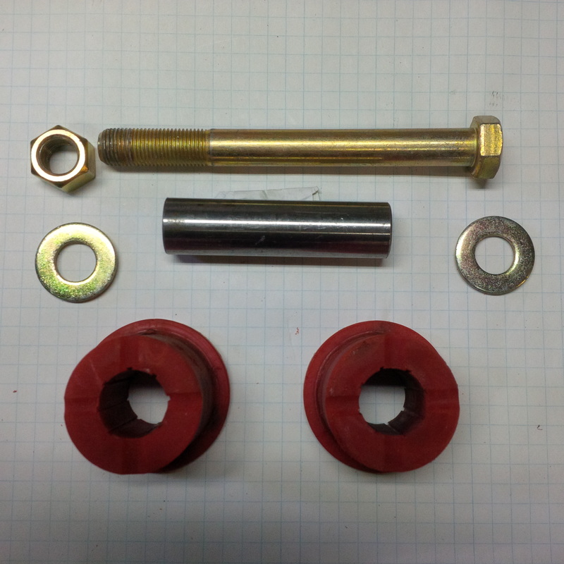
After I cut the poly bushings shorter, I also filed grooves in the bushing ends so that when the grease fittings are used, there would be several passages between the bushings to allow the grease to make its way easily to the center bore on the bushings. Here is a picture of the stock sleeve and the custom length stainless steel sleeve showing the difference in length. The second picture shows the shortened bushings and control arm bolt. I'll swap the nut for a self locking type during the final installation.
After I cut the poly bushings shorter, I also filed grooves in the bushing ends so that when the grease fittings are used, there would be several passages between the bushings to allow the grease to make its way easily to the center bore on the bushings. Here is a picture of the stock sleeve and the custom length stainless steel sleeve showing the difference in length. The second picture shows the shortened bushings and control arm bolt. I'll swap the nut for a self locking type during the final installation.
|
|
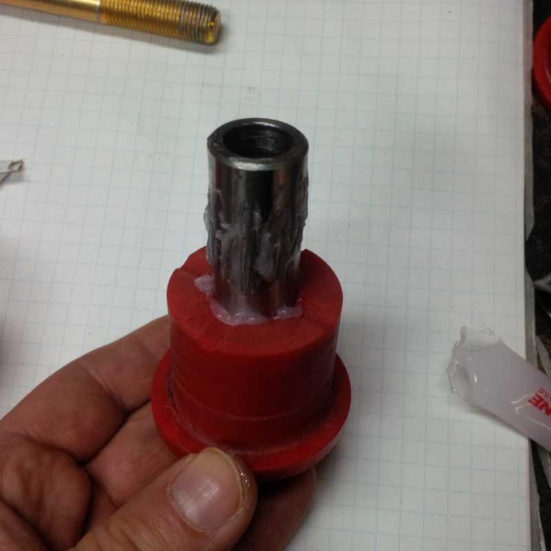
Here is what the parts looks like assembled together and ready for installation.
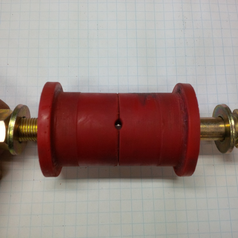
During installation of the poly bushings, I applied a generous amount of the supplied lubricant. It made installation into the control arm much easier.
|
|
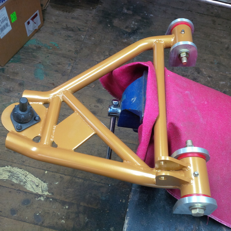
Since I haven`t welded the control arm lugs to the cradle yet, I installed them on the control arms for a photo opportunity.
The final step today was to install a new ball joint which I had acquired as a set from my friend Dave in a trade for some fiberglassing material. I am very happy with the fit and finish of these control arms and the work to design exactly what I wanted was well worth the effort. I couldn`t resist the chance to slip the driver side control arm under the car to see how it looks sitting on the cradle. Time to assemble the passenger side control arm now.
|

|

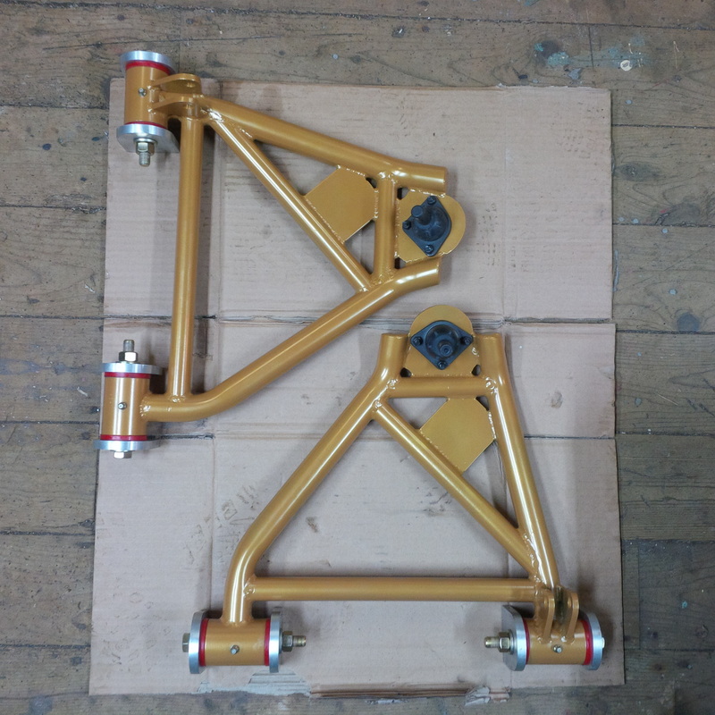
Here are both of the rear control arms assembled with bushings and ball joints.
Dec 22 2015
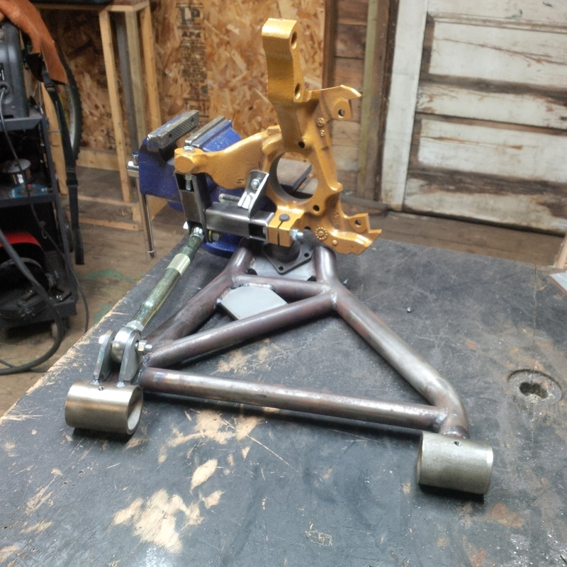
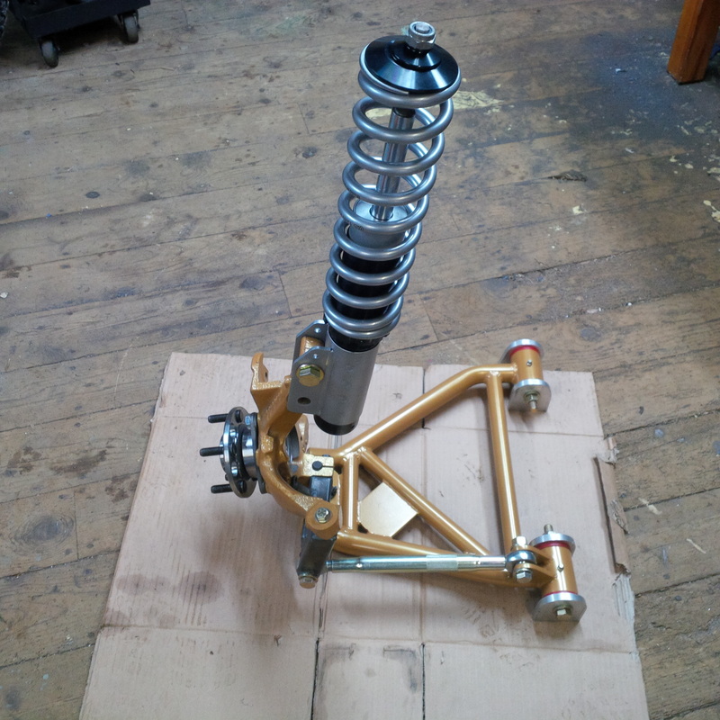
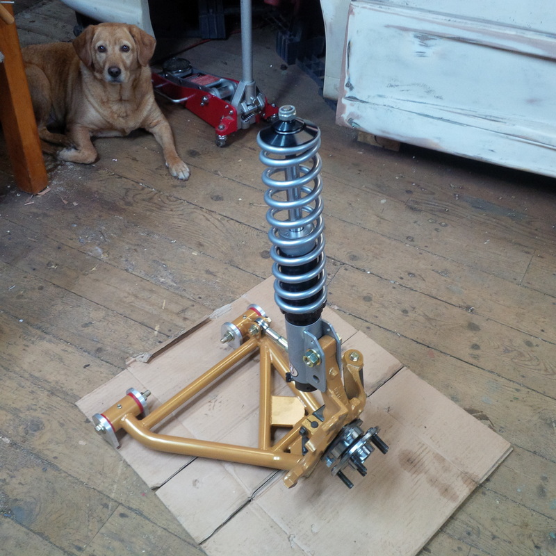
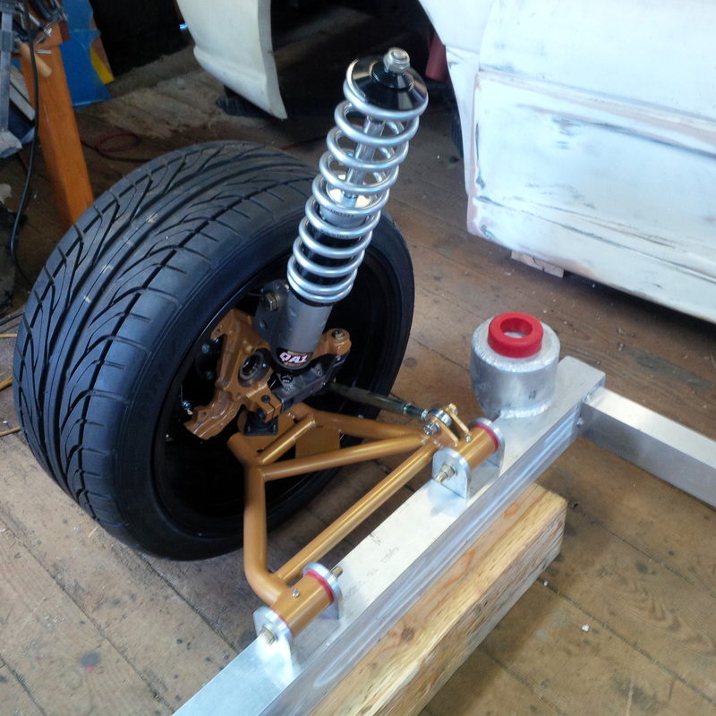
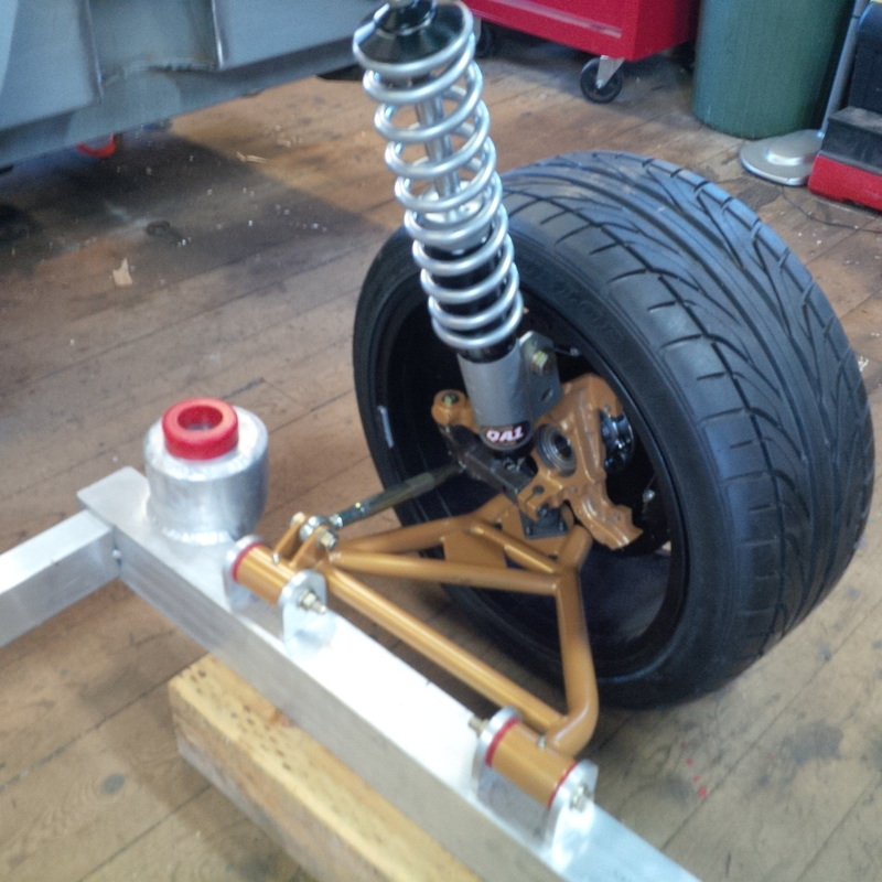
Before I get the last of the parts powder coated, I thought I would assemble the driver side rear suspension just to see how things fit together. It all fits like a glove and looks pretty robust. Even Rosie approves. :)
Before I get the last of the parts powder coated, I thought I would assemble the driver side rear suspension just to see how things fit together. It all fits like a glove and looks pretty robust. Even Rosie approves. :)

|
|
Dec 26 2015
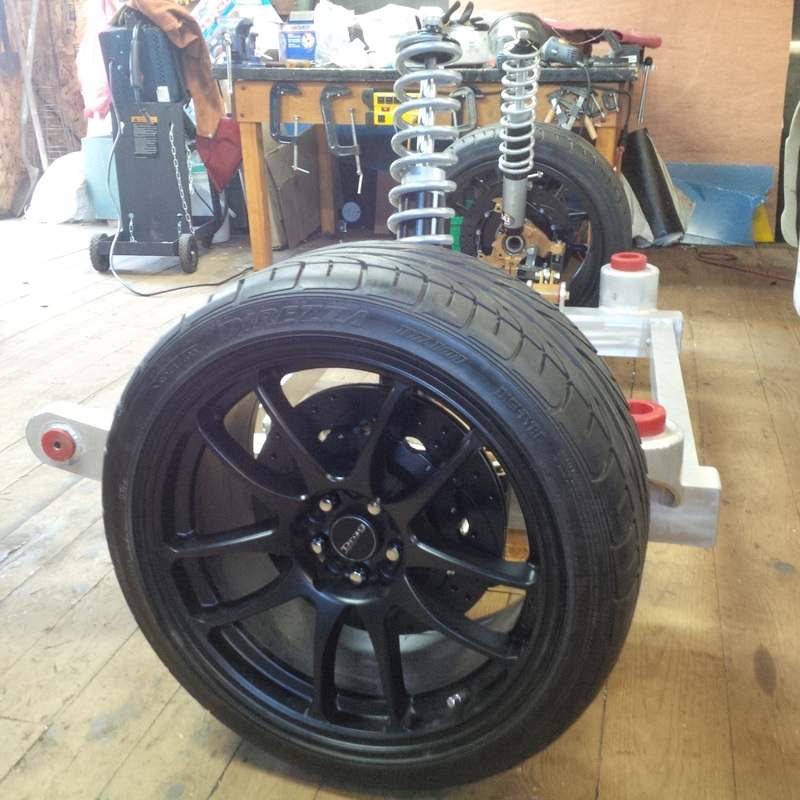
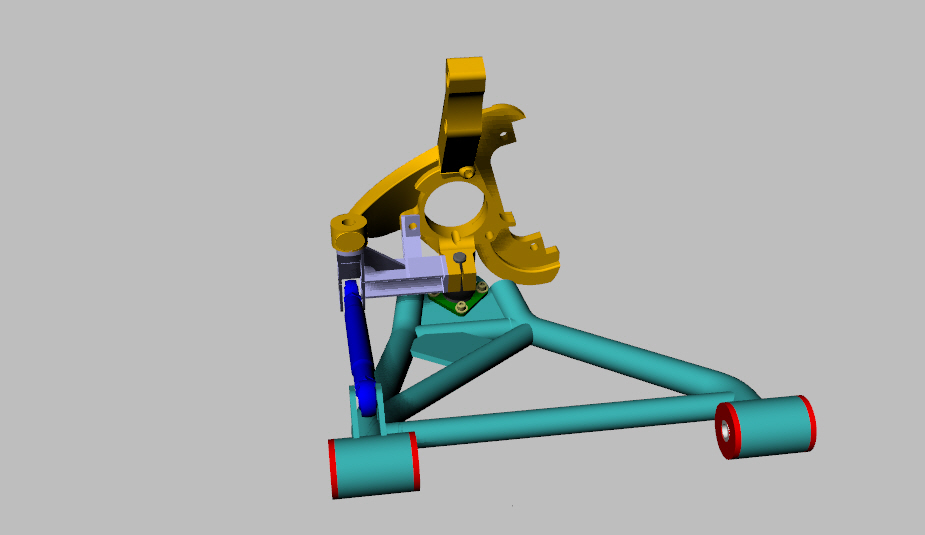
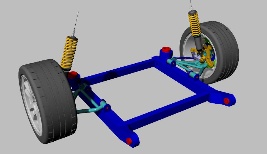
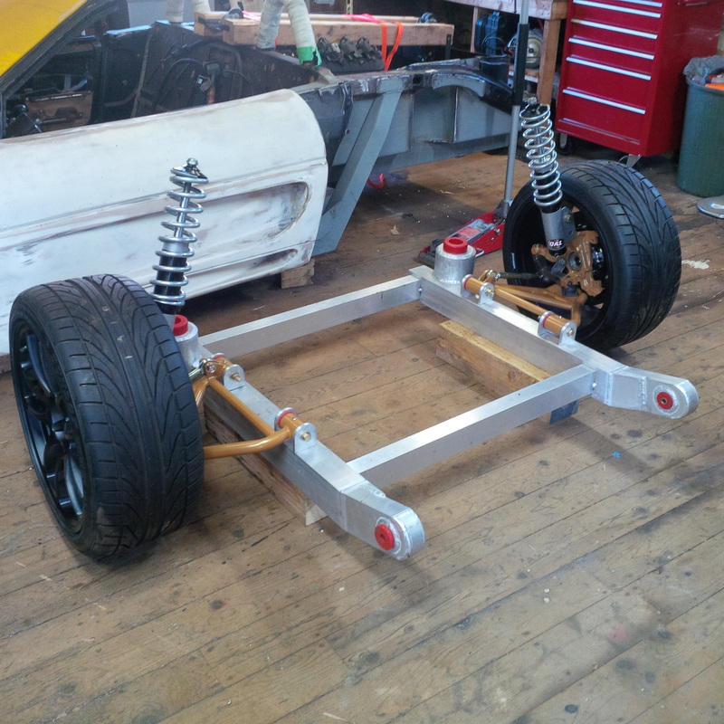
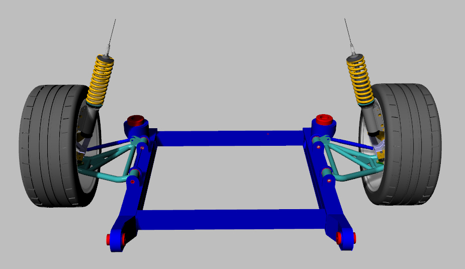
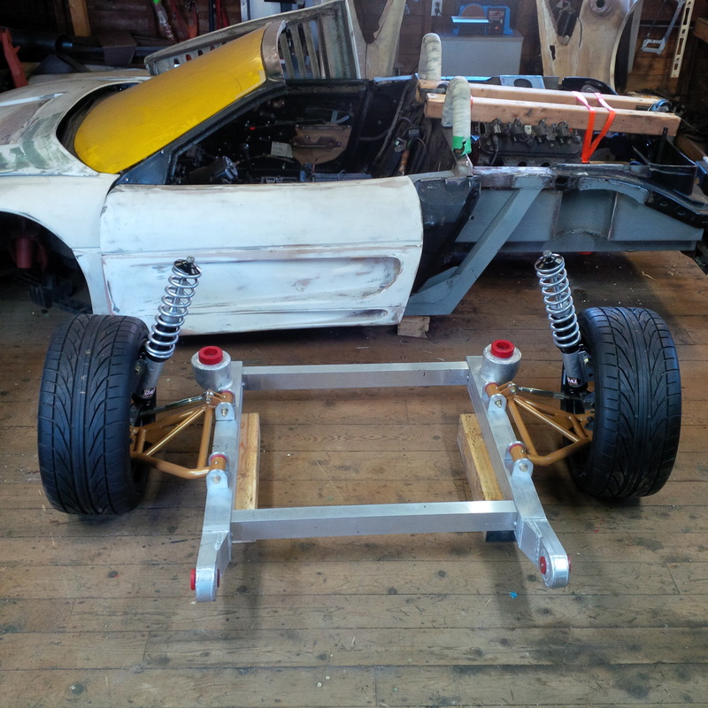
Well, I thought I'd spend the day mocking up all the rear suspension components to confirm that everything fits as designed and that the rear wheelbase is where I want it before I send the last of the parts such as bump steer linkages and spindles out for powder coating. Here are a couple images from my 3D model with the rear wheels in place along with pictures of the actual assembly. Btw, the parts are balanced precariously as the control arm lugs are not welded to the cradle yet. So if something looks a little out of line, its only because everything is slowly rolling out of alignment on my old wooded shop floor as I take pictures. Also, the struts in the 3D images are set at ride height and the actual struts in the photos are fully extended as there's no weight on them.
Well, I thought I'd spend the day mocking up all the rear suspension components to confirm that everything fits as designed and that the rear wheelbase is where I want it before I send the last of the parts such as bump steer linkages and spindles out for powder coating. Here are a couple images from my 3D model with the rear wheels in place along with pictures of the actual assembly. Btw, the parts are balanced precariously as the control arm lugs are not welded to the cradle yet. So if something looks a little out of line, its only because everything is slowly rolling out of alignment on my old wooded shop floor as I take pictures. Also, the struts in the 3D images are set at ride height and the actual struts in the photos are fully extended as there's no weight on them.
|
|
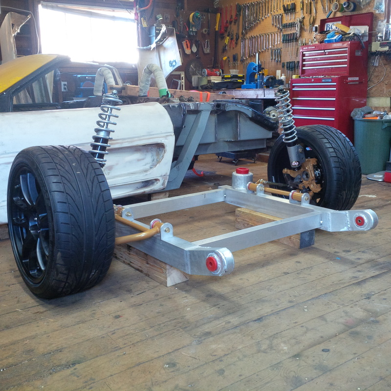
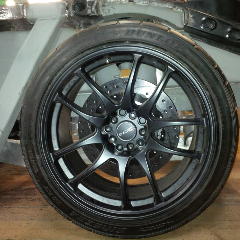
I have to be honest, I am a little surprised at how small those 13" rotors look inside the 18" rear wheels. Oh well... lots of room for the calipers atleast.