the 6" Chassis Stretch
Oct 20 2017
Here is a little hint as to what I have been working on this past month. I'll fill in more details this weekend regarding this new direction.
Here is a little hint as to what I have been working on this past month. I'll fill in more details this weekend regarding this new direction.
Oct 21 2017
Ok. So here is the explanation that goes along with the above, poorly executed photoshop of a perfectly fine F355. I agree with my friend Dave that the stretched 355 doesn't look that out of place until you compare it to the stock length 355. Then it seems that something is amiss. I am hopeful though that when it comes time to really design the shape of the rear half, that I can make the car look as pleasing to the eye as the stock length does.
For those that are familiar with the pitfalls and challenges of installing a longitudinally mounted V8 in a stock or mildly stretched Fiero chassis, I'll ask that you bare with me while I briefly outline the challenges I faced and my attempts so overcome these challenges. In a nut shell, converting the stock transversely mounted engine arrangement of a mid engine chassis to a longitudinally mounted arrangement means that the drive shafts get shifted rearward and thus out of alignment with the location of the rear suspension. Add to this fact that the longitudinal engine, in my case an LS3 V8, also requires a longitudinal style transmission, in my case an Audi 01E. Together, the longer longitudinal engine and longitudinal transmission push the drive shaft line atleast 12" past the plane of the rear suspension. I attempted to compensate for a portion of this misalignment by pushing the engine as far forward as possible. As well, I completed a 3" chassis stretch in the engine compartment to achieve the stock wheelbase of the 355. To their credit, there have been a number of talented car builders who have been successful with their longitudinal installations. Some have selected engines that are physically shorter like the Audi V8 or various V6 engines and some have moved the engines much farther forward by notching the firewall to clear the front mounted engine auxiliaries. Unfortunately for me, I had my heart set on the LS3 which is not a particularly short engine and the additional transverse chassis structure I added to the rear side of the firewall to compensate for the loss of the roof structure meant that I was quite limited in moving the driveline forward; but I was always aware of this limitation. I did remove engine driven water pump from the front of the engine and I also reversed the engine intake manifold so that my LS3 could move as far forward as possible behind the firewall. I was left with about 8" of misalignment between my rear suspension and the output shafts of the 01E transmission.
I narrowed down my options to overcoming the remaining driveline issues to two (2) possibilities:
1. select shafts and cv joints that could handle the misalignment
2. design a drive line that artificially corrects for the misalignment
As a note, these options were briefly outlined in the Drivetrain / Driveline section of my blog. Even though I am giving a more detailed description here, I will leave the original August 6 post in the Driveline section as it represents where I was with my design on that date.
1. Custom Drive Shafts
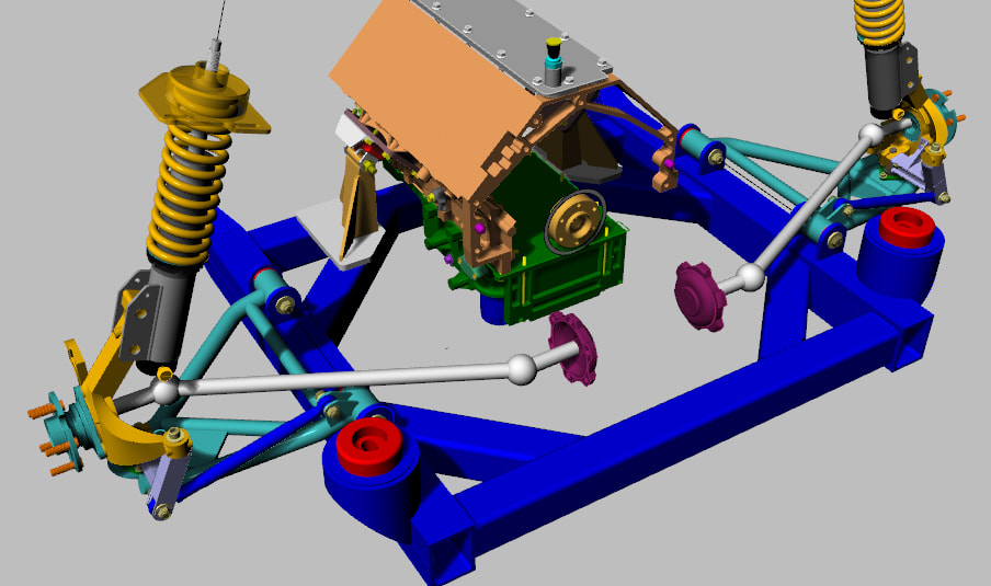
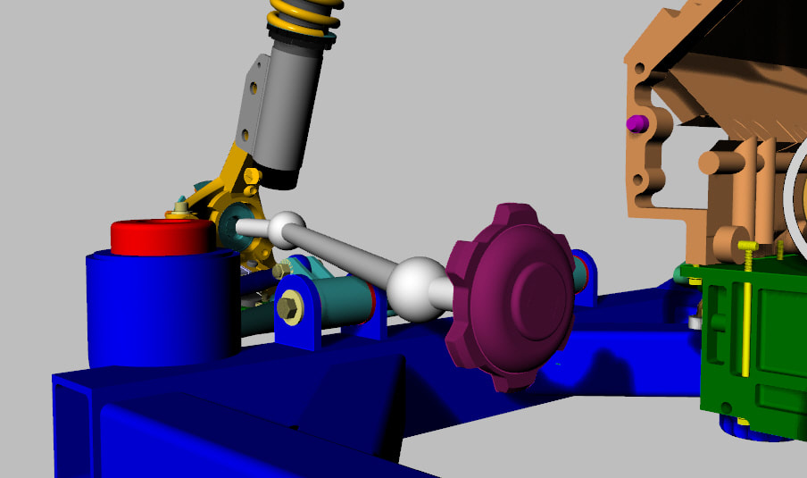
As you can see from these images from my 3D chassis model, the 8" of misalignment created a shaft line with approximately 25 degrees of offset. While this is not beyond the realm of possibility for high quality CV joints ( according to a number of manufactures and real world experiences by other builders), it's certainly approaching the limits of practicality and reliability for a sports car ( again, according to a number of websites). On top of that large shaft angle, I also discovered from my 3D model that the shaft would likely interfere with the lower control arm bushings. This was a deal breaker as I had no intention or desire to redesign and rebuild my rear suspension.
2. Driveline Alteration
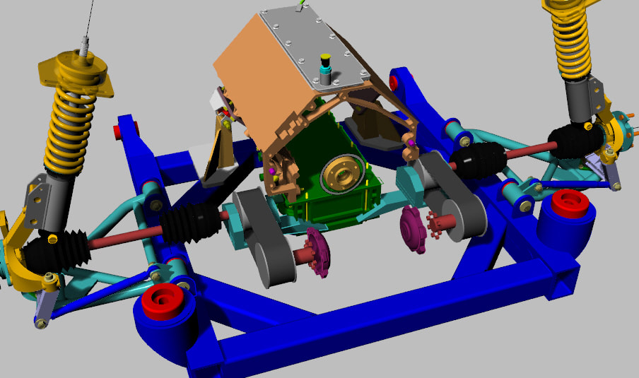
The second option I explored was to alter the driveline so that the resulting shaft angles were well within a normal range and also eliminate interference between the various suspension components and the shaft line. I looked at using offset gearboxes on each side of the transmission to provide the needed 8" of shaft offset but these would be complicated to support, lubricate and cool as well as be quite expensive with questionable reliability for the power and shaft rpm of my engine / transmission combination. The alternative was to design a belt drive that would provide the 8" offset for each driveshaft. I have used Gates driveline products before for work projects but never for a gas engine in a car. They have a very interesting online design tool that allows you to set your design parameters and select the type of Gates products you want to use. I spent over 3 months on and off, using their design tool, tweeking input parameters and products and each time, the software would provide a list of notes regarding areas were my design exceeded their product specification. On top of that, the power source choices did not include gas engines with a 6 speed manual transmission installed in a sports car. For this fact, I was always leery of the results as selecting an electric induction motor with soft start controller was hardly representative of a middle age guy in a custom built sports car, sitting at a red light next to a young guy in his foreign built ....whatever the hell that is. ha-ha-ha
Here is a basic arrangement of what the belt drive set up would look like. It would use Gates Poly Chain GT Carbon belts with matching Poly Chain GT2 Sprockets. The driver sprocket/ sheave would be mounted on each of the Audi output shaft flanges and the driven sprocket / sheave would be supported by bearings that were supported on a foundation which extends from the sides of the aluminum bell housing adapter plate. This would give the needed 8" of offset required for a relatively straight driveline.
I do feel that the design, while still in its infancy, has some merit and perhaps someday I will revisit it again. I will not detail all the work that I did on this design but I will explain briefly describe the hurtles that I came up against while trying to achieve a suitable arrangement that stayed within the operating range of the selected components.
In order to handle all of the power that one shaft might see in an extreme operating condition with a limited slip differential, the sprockets / sheaves had to be larger in diameter than I am showing in my 3D model in order to get the necessary belts / sprocket contact surface area. The sprocket diameter grew to the point where there was no longer any separation between the driver and driven sprocket. Remember that I only needed 8" of shaft offset which also put the support bearings in line with the bell housing adapter plate. If I increased the sprocket separation, the driven sprocket would have to move forward and away from the adapter plate. I felt this drive system had to be mounted on the bell housing adapter plate because it had to move with the engine and transmission which are bolted together and on poly mounts. Having a belt drive with one end connected to the flexing engine / transmission and the other end mounted on the fixed engine cradle would surely destroy the belt under load or atleast throw it off the sheaves. Both situations would be bad.
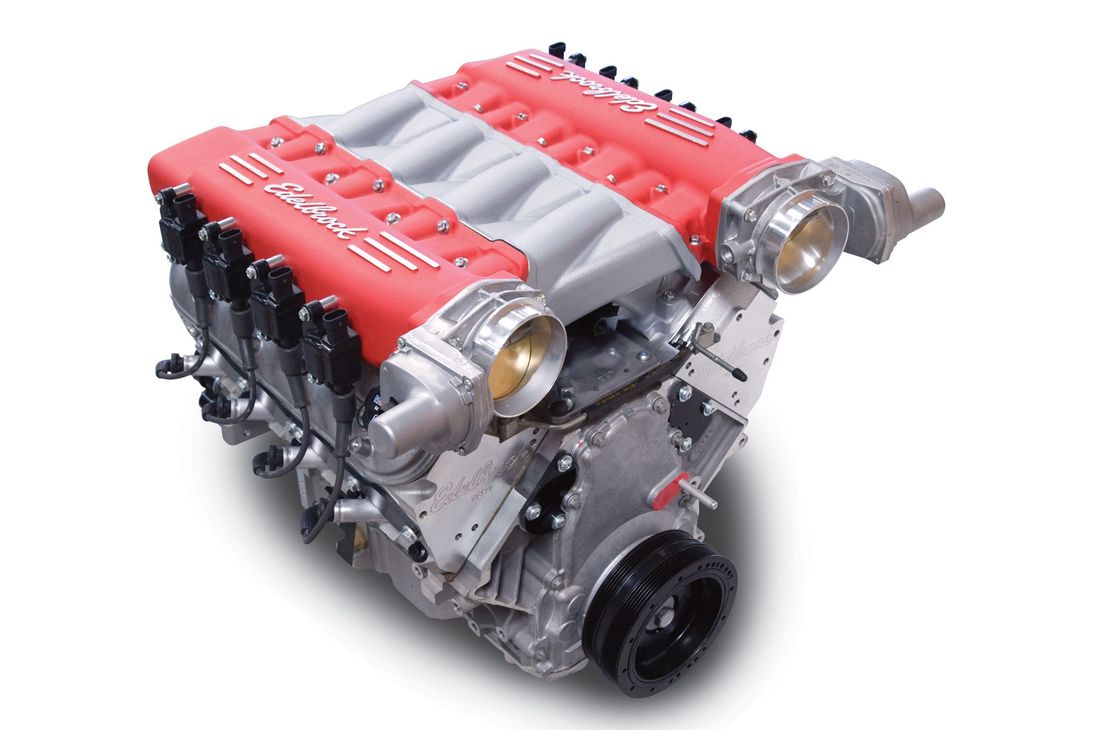
So, having a design that was operating at its threshold of its power transmission was not acceptable to me considering that if the drive failed on one side while operating, it could create a dangerous condition that could send the car in the wrong direction suddenly. As well, my design was based on the maximum power of the stock LS3 crate engine, 430 hp. That left no room for increasing the power at some time in the future and that was something I could not rule out. There are so many amazing and very cool upgrades available to the LS3 that would make this car even more fun to build and drive. For instance, the Edelbrock LS Cross Ram Intake with duel throttle bodies. Hmmmm twin turbo 355 perhaps? :)
So, as you may have guessed by the heading of this section, 6" Chassis Stretch, I have decided to forgo a custom designed drive line in lieu of a further chassis modification that moves the rear suspension back from its current position so that the transmission output flanges are more inline with the rear suspension, producing a driveline that is well within normal parameters and hopefully easier to build and more reliable to operate.
I will outline each of the modifications required to make this change in their respective directories so that its easier to find the details of each change in the future.
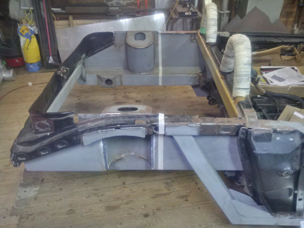
To begin, I plan to cut the chassis between the strut towers and the rocker reinforcements that I added earlier in the build. This will mean a fairly easy cut and then fill the resulting gap in the structure with suitable steel elements. In this photo, the tape indicates where the cut is to be made.

