Cross Member
Jan 1 2016
Well Happy New Year everyone. Its hard to believe 2016 is here already. I think this is the first time I typed 2016 and I am sure I will spoil a few cheques over the next few weeks. :(
While I have not been doing any actual work on the front suspension, I have certainly given it much thought throughout the project progress, especially during the development of the rear suspension. And like the rear suspension, I have a couple goals to achieve with the new front suspension.
First of all, I need to widen the track from the stock set up. At this moment I don't have an exact track width in mind but I do know I have to make it suit the future 355 style body. My goal is to match the track width of my friend Dave as we will be building almost identical bodies. I am very lucky that he has his front suspension completed so I have a precise measurement to achieve. I am visiting him tomorrow and one of my goals is to take measurements of his front and rear track widths.
Second on my list is to lower my front suspension in relation to the stock height, again, to suit the body styling of the 355. In my mind, most or all of this will be achieved using lowering front spindles. I may either design and build these or purchase a set from a supplier.
Third on the list of things to achieve is to improve the front suspension geometry. This will certainly be a challenge for me, even more so than the rear suspension was as there is alot more going on in the front, including all the above mentioned changes that I want to achieve. This improvement will also include the use of coil overs, preferably QA1's if possible.
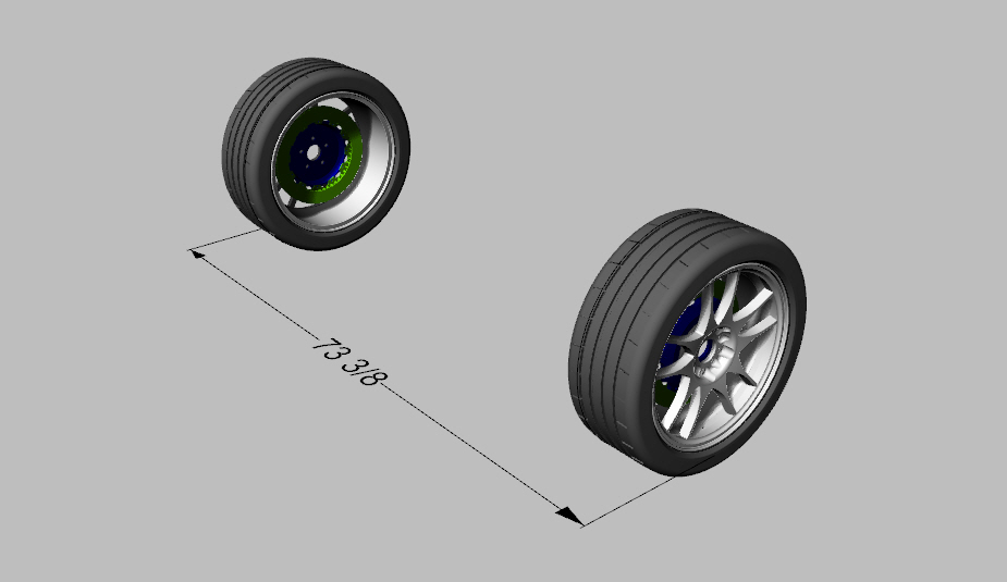
The final goal of my front suspension upgrade will be to include upgraded brakes, similar to the Wilwood units fitted on the rear suspension. As I have already purchased my wheels which are 17" versions of my rear 18" wheels, I know I will be able to fit 13" rotors like the rear wheels.
With all that said, I have to first decide on a starting point for this project. I can either purchase a complete front suspension assembly like the Arraut Motorsports Slalom Front Suspension, design and build my own front suspension from scratch or use the stock front cross member and design my suspension around this foundation. While this last method might be more economical, I suspect that I will be too limited in my suspension design and might not be able to optimize the geometry. Regardless, I think this will be my starting point for the suspension analysis and let the results guide the direction of the further development.
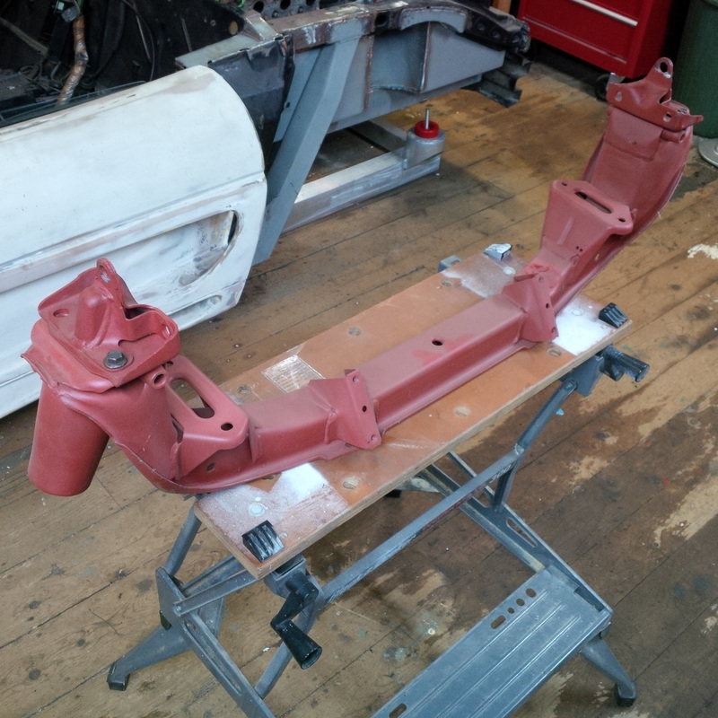
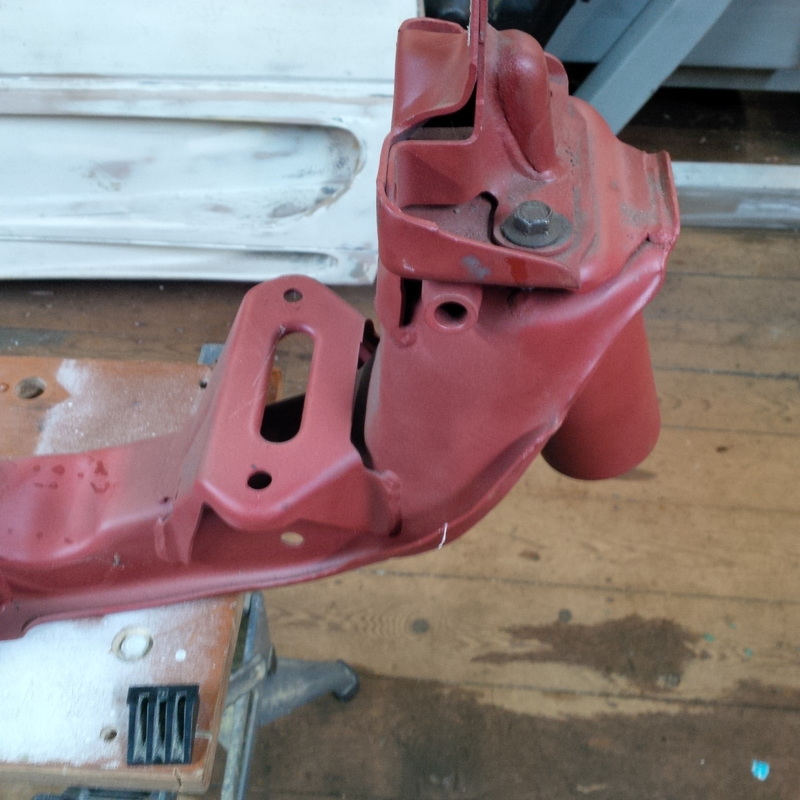
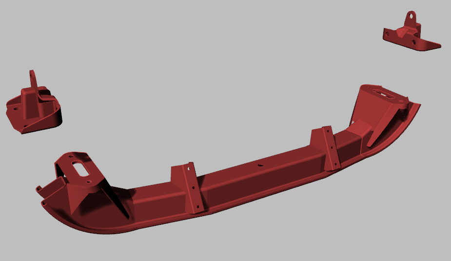
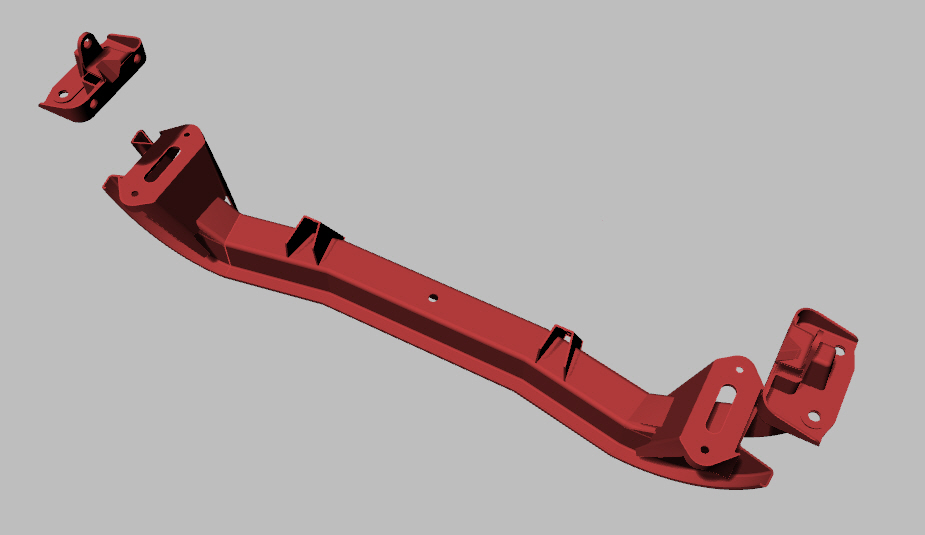
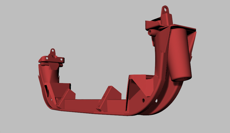
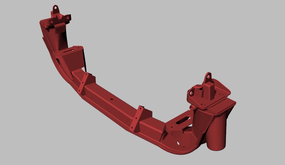
Here is my front cross member. It is in mint condition as it has very few km's on it and I had it sand blasted and sprayed with marine grade primer many years ago.
Well Happy New Year everyone. Its hard to believe 2016 is here already. I think this is the first time I typed 2016 and I am sure I will spoil a few cheques over the next few weeks. :(
While I have not been doing any actual work on the front suspension, I have certainly given it much thought throughout the project progress, especially during the development of the rear suspension. And like the rear suspension, I have a couple goals to achieve with the new front suspension.
First of all, I need to widen the track from the stock set up. At this moment I don't have an exact track width in mind but I do know I have to make it suit the future 355 style body. My goal is to match the track width of my friend Dave as we will be building almost identical bodies. I am very lucky that he has his front suspension completed so I have a precise measurement to achieve. I am visiting him tomorrow and one of my goals is to take measurements of his front and rear track widths.
Second on my list is to lower my front suspension in relation to the stock height, again, to suit the body styling of the 355. In my mind, most or all of this will be achieved using lowering front spindles. I may either design and build these or purchase a set from a supplier.
Third on the list of things to achieve is to improve the front suspension geometry. This will certainly be a challenge for me, even more so than the rear suspension was as there is alot more going on in the front, including all the above mentioned changes that I want to achieve. This improvement will also include the use of coil overs, preferably QA1's if possible.
The final goal of my front suspension upgrade will be to include upgraded brakes, similar to the Wilwood units fitted on the rear suspension. As I have already purchased my wheels which are 17" versions of my rear 18" wheels, I know I will be able to fit 13" rotors like the rear wheels.
With all that said, I have to first decide on a starting point for this project. I can either purchase a complete front suspension assembly like the Arraut Motorsports Slalom Front Suspension, design and build my own front suspension from scratch or use the stock front cross member and design my suspension around this foundation. While this last method might be more economical, I suspect that I will be too limited in my suspension design and might not be able to optimize the geometry. Regardless, I think this will be my starting point for the suspension analysis and let the results guide the direction of the further development.
Here is my front cross member. It is in mint condition as it has very few km's on it and I had it sand blasted and sprayed with marine grade primer many years ago.
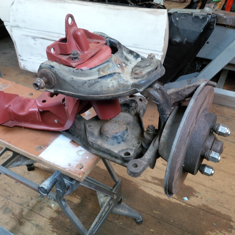
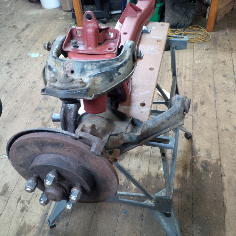
The first step for me will be to model this cross member in Rhino so I have an accurate 3D model of the part. I'll also model the stock suspension components so that I can do an analysis of the stock geometry as a baseline prior to further development. Here is the stock control arms and spindle for the driver side. Its a little dirty but still in good condition.
Jan 2 2016
Had a great visit with Dave today and we spent the afternoon chatting about our project cars. We also got some measurements of his front and rear track width that I will use as a starting point for the design of my front suspension. I should clarify that these measurements are not actually "track width" as I am measuring from the outer most surface of the tire to the outer most surface of the opposite tire. It is this measurement that I will use to ensure that my wheels / tires are set to the edge of the wheel wells for cosmetic reasons. Here is the track width we recorded for the front wheels.
Had a great visit with Dave today and we spent the afternoon chatting about our project cars. We also got some measurements of his front and rear track width that I will use as a starting point for the design of my front suspension. I should clarify that these measurements are not actually "track width" as I am measuring from the outer most surface of the tire to the outer most surface of the opposite tire. It is this measurement that I will use to ensure that my wheels / tires are set to the edge of the wheel wells for cosmetic reasons. Here is the track width we recorded for the front wheels.
Jan 10 2016
Today I started the process of drawing the front cross member in Rhino to add to my car 3D model. After 6 hours of measuring and drawing, this is all I have to show for the effort. That is one complicated, convoluted part to draw. At this point I have the key surfaces and connection points between the cross member and the chassis completed so I can atleast start designing a new custom cross member that will be the foundation for my new suspension geometry.
Today I started the process of drawing the front cross member in Rhino to add to my car 3D model. After 6 hours of measuring and drawing, this is all I have to show for the effort. That is one complicated, convoluted part to draw. At this point I have the key surfaces and connection points between the cross member and the chassis completed so I can atleast start designing a new custom cross member that will be the foundation for my new suspension geometry.
Jan 12 2016
Here is the front cross member model complete. Now time to start designing a new cross member to support the suspension geometry I require ( ie: wide track, drop spindles, improved suspension geometry)
Here is the front cross member model complete. Now time to start designing a new cross member to support the suspension geometry I require ( ie: wide track, drop spindles, improved suspension geometry)
Feb 1 2016
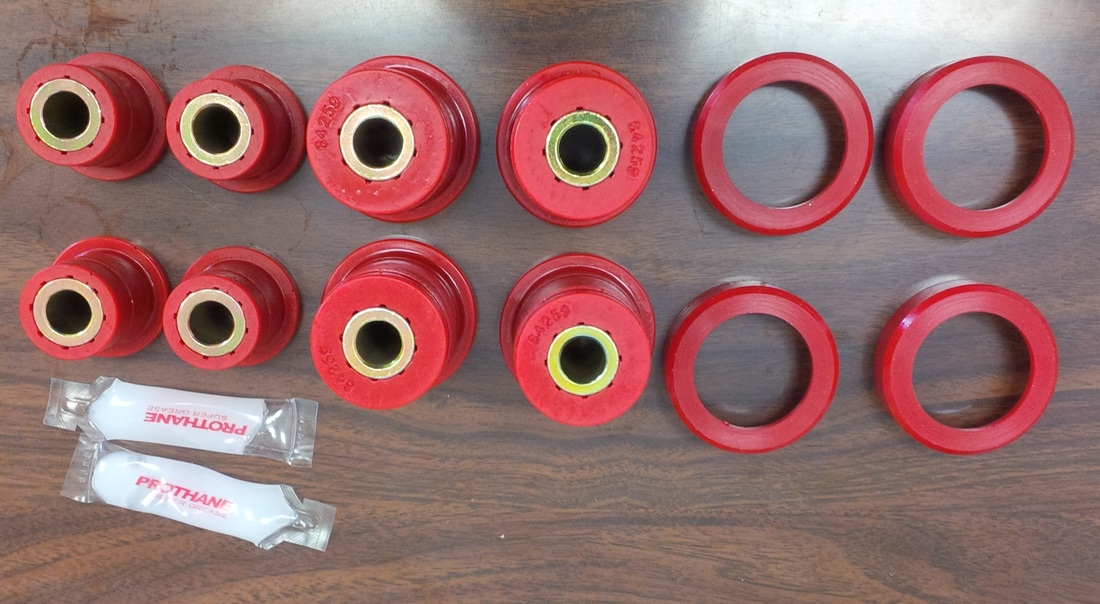
Here are the poly bushings for the upper and lower control arms. I ordered them from the Fiero Store. I'll be glad when the Canadian dollar is back on par. Ouch :(
Here are the poly bushings for the upper and lower control arms. I ordered them from the Fiero Store. I'll be glad when the Canadian dollar is back on par. Ouch :(
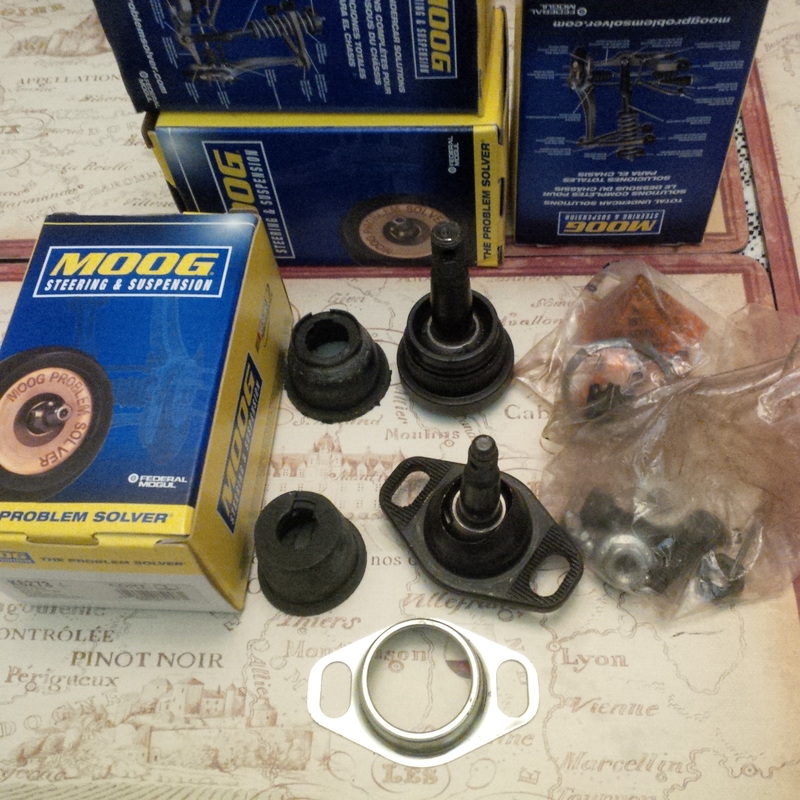
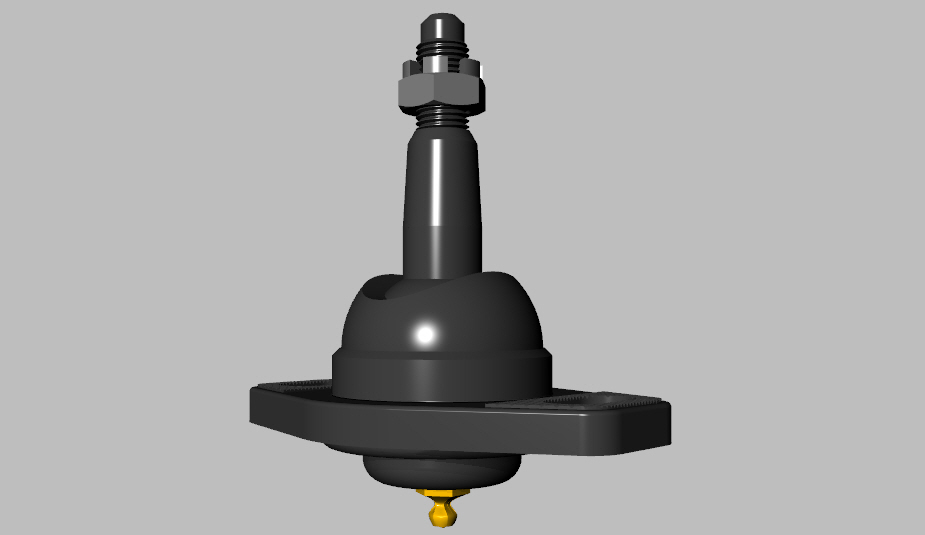
Here are the Moog upper and lower ball joints that just arrived today as well. I may have to get some red poly dust boots to match the control arm bushings :)
Feb 3 2016
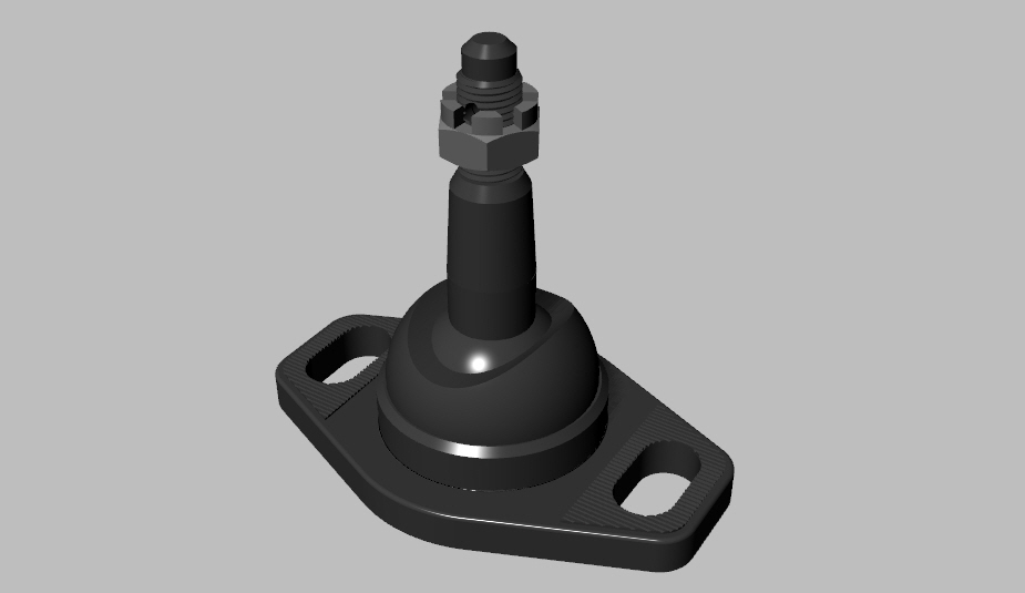
Slowly adding the parts to my 3D model......... one piece at a time.
Slowly adding the parts to my 3D model......... one piece at a time.
|
|

Feb 4 2016
The very very very early stages of the front cross member development. Just putting the parts in their general positions at this stage. I am seriously thinking of doing an aluminum front cross member like I did for the rear engine cradle. Time will tell...................................................
The very very very early stages of the front cross member development. Just putting the parts in their general positions at this stage. I am seriously thinking of doing an aluminum front cross member like I did for the rear engine cradle. Time will tell...................................................
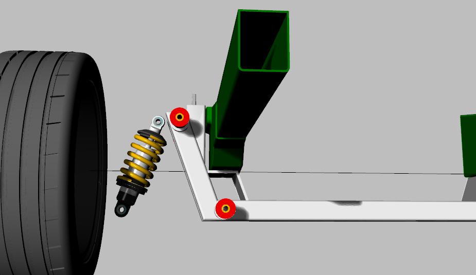
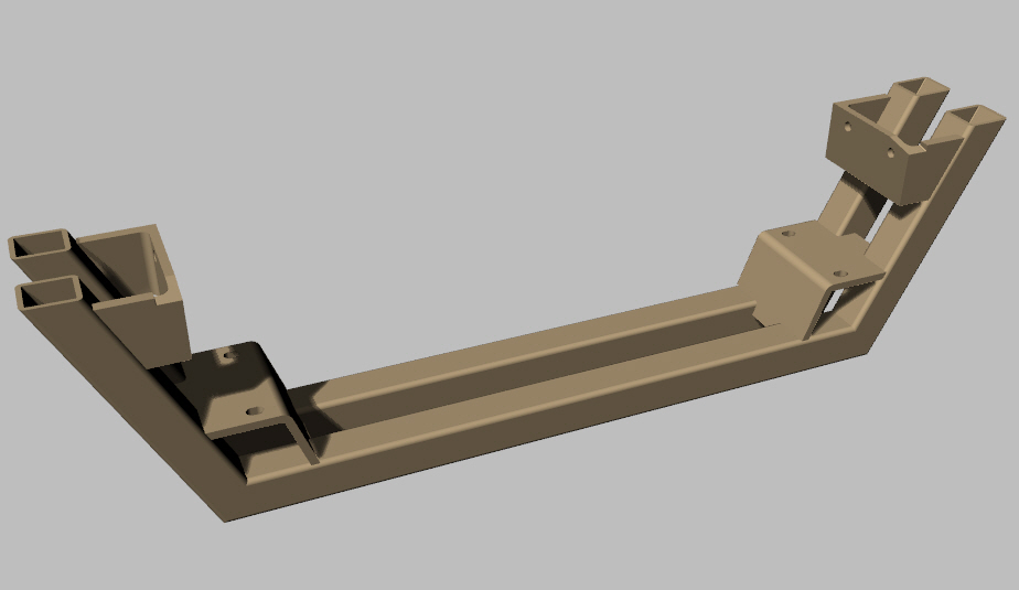
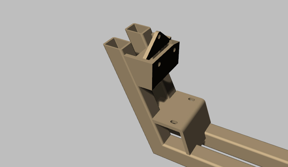
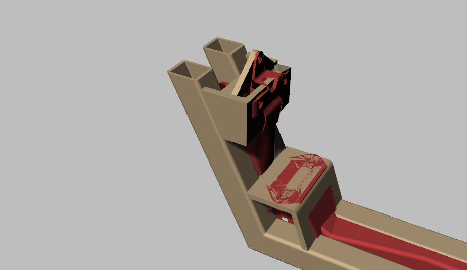
Using my model of the stock front cross member ( ghosted brown in the first image) as a guide to pick up the stock chassis attachment points, I roughed out the basic geometry of the required structure. This is a first draft utilizing stock material extrusions and plate thicknesses to test the concept. I added the control arm bushings to help visualize the structure but I have not yet analyzed the geometry of the suspension at this point. It is quite likely that when I look deeper into the kinematics, the cross member structure may have to change significantly. Time will tell :)

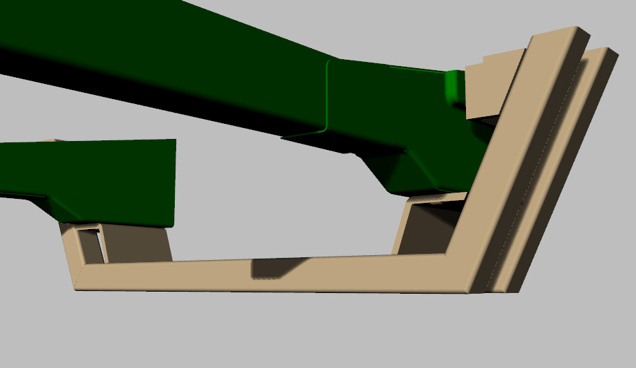
Here is an image showing the stock front frame rails and how the new cross member will snuggle in tight.
Feb 5 2016
Well its Friday afternoon and almost quitting time so I thought I'd throw some rough geometry on my drawing to get an idea of what the control arms might look like. Again, this is just a rough first draft with no analysis done so bare with me for now. This is purely an artistic attempt to allow my brain to decompress before the weekend. :)

A little further development of the drop spindle.
Feb 14 2016
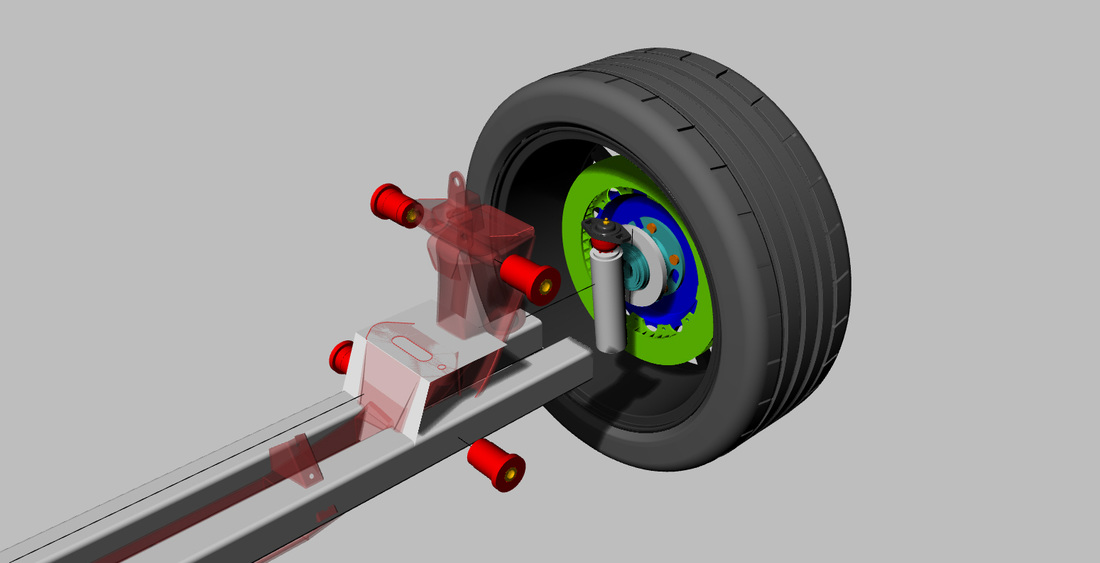
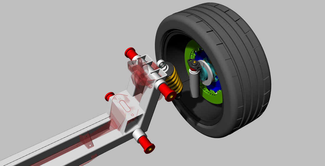
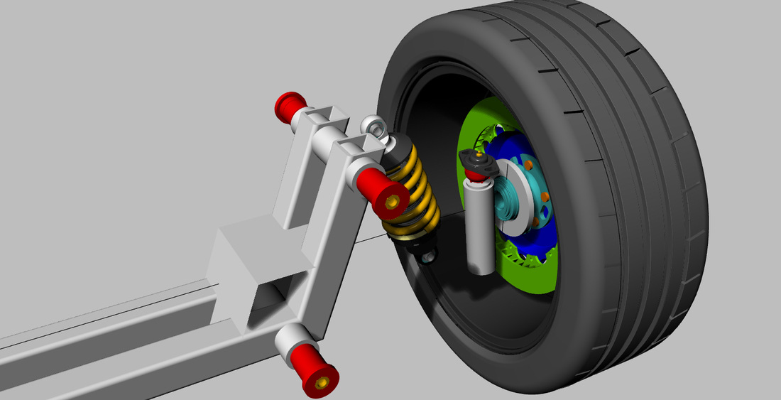
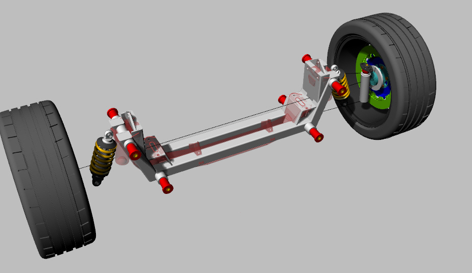
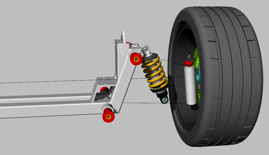
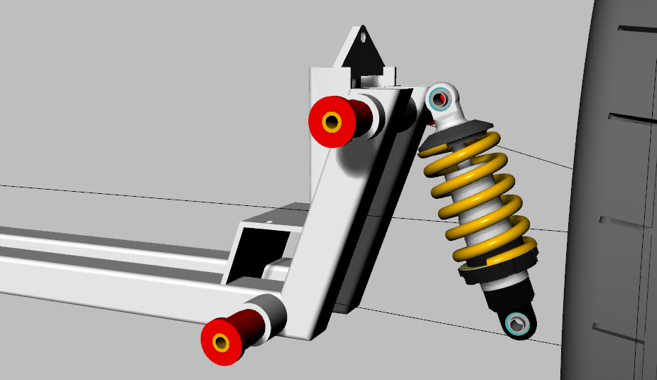
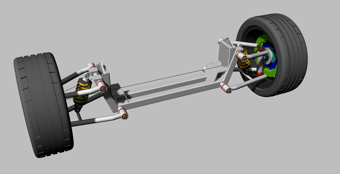
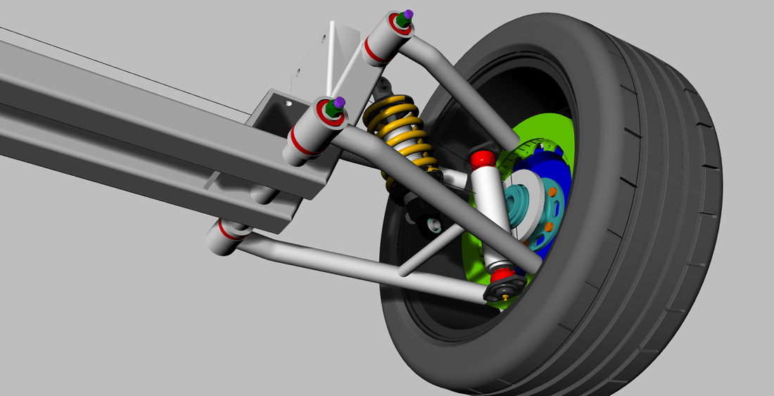
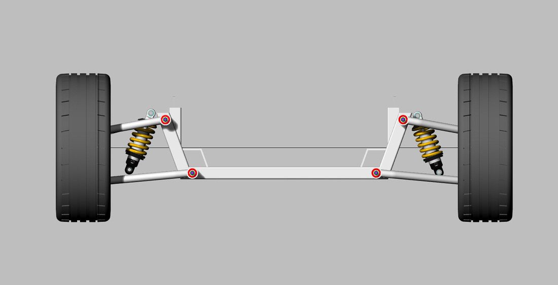
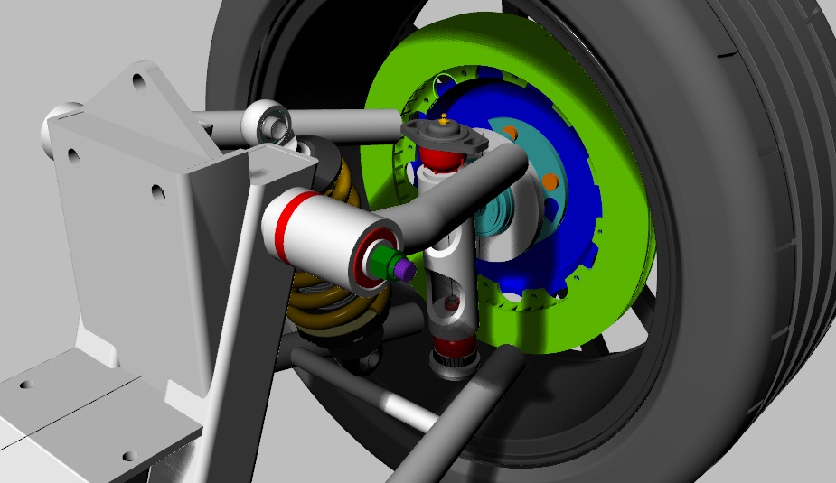
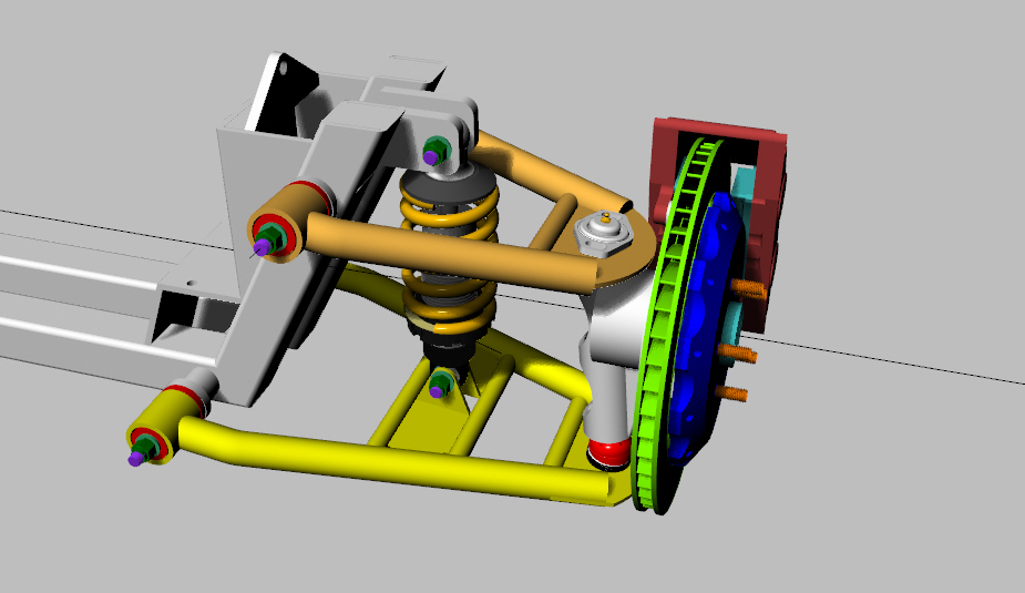
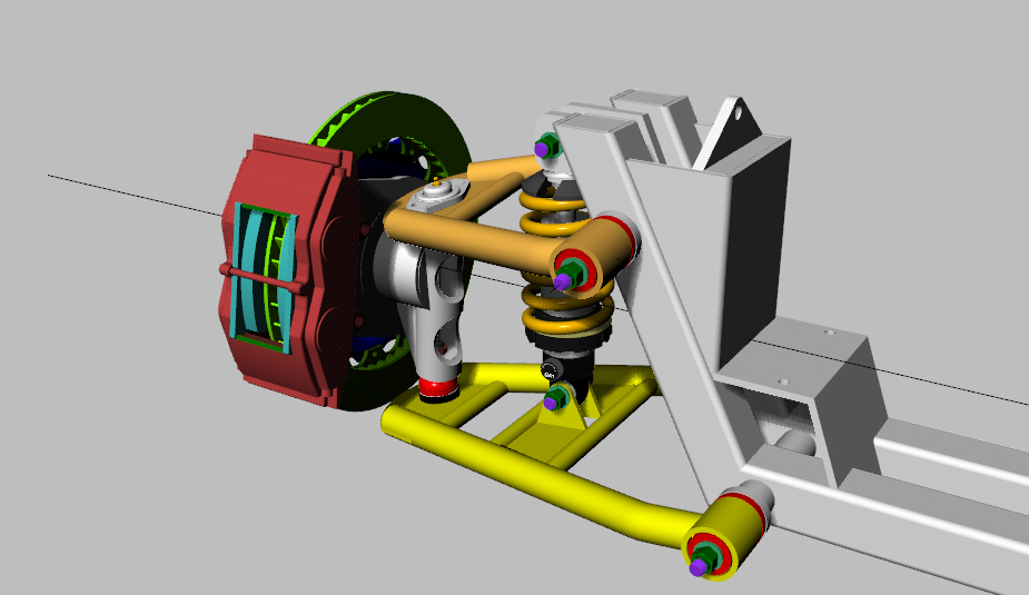
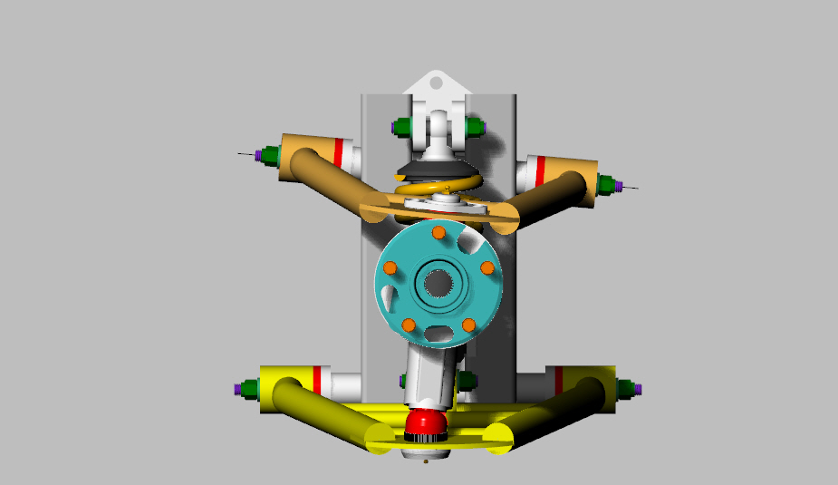
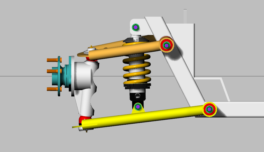
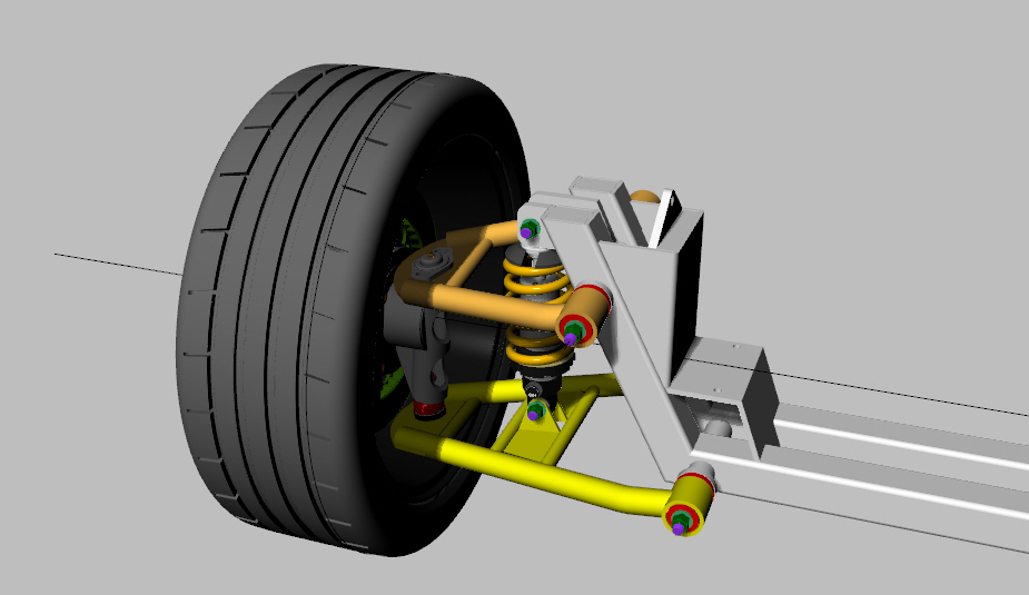
The work continues on the development of the drop spindles and control arms, trying to get the kingpin angle, camber and caster as well as anti dive all accounted for. Holy smokes it gets complicated and I still have work left to refine all the parts. But I have everything close enough that I can replace the individual components with a wire frame model which will then allow me to complete an analysis of the geometry through the suspension range of motion. I am sure there will be further refinement of the components so there is little reason to spend time doing final details of the component construction until I am happy with the results of the dynamic analysis. When I have the results, I will add them to the website along with a subsection for each component detailing the design and construction.
Here are a few updated images from the current 3D model.

March 6 2016
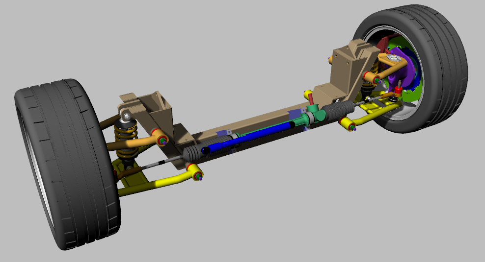
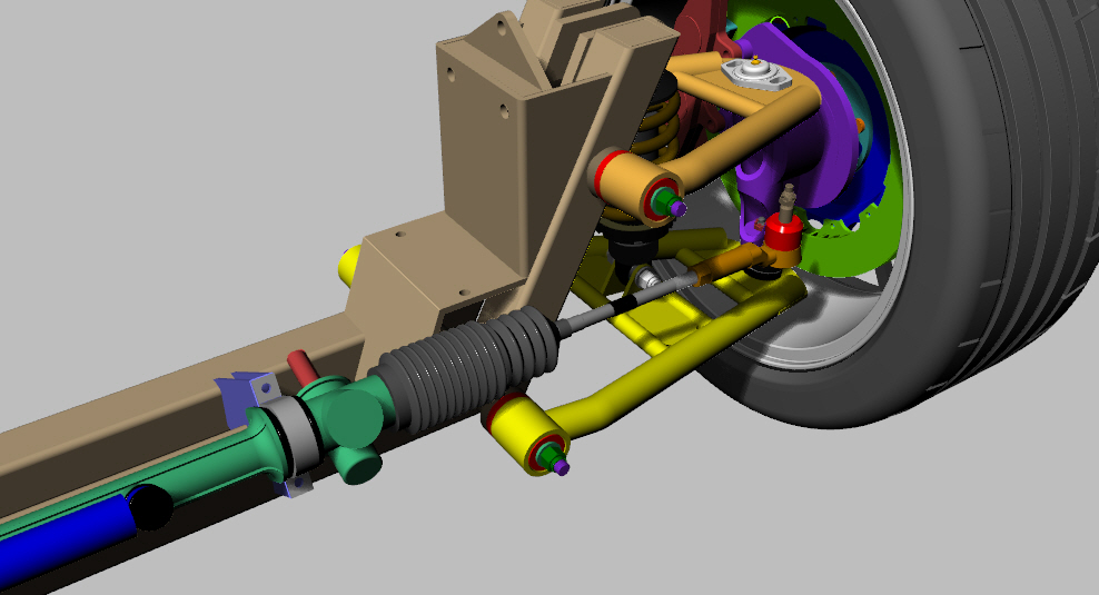
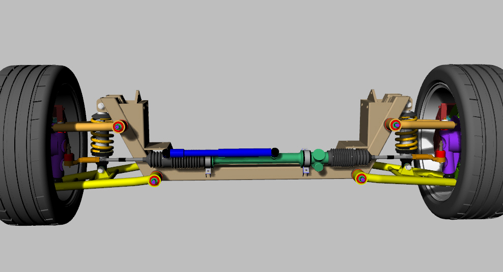
Here is the front suspension with the stock steering rack added to the drawing. Of course I'll have to extend the reach of the tie rods to reflect the wider track of the front end. I'll have to add the steering knuckle to the new drop spindles and then test the geometry through jounce and rebound to get the data on toe in change.

March 7 2014
By Dave
The addition of the steering rack makes that front end look like you're ready for fabrication. Kudos for the awesome 3D work. Just be sure to keep those inner tie rod joints lined up with the upper and lower inner control arm pivot plane, and the outer tie rod ends lined up with the outer ball joint plane as viewed from the front. If you don't, you'll end up with bump steer.
Response by Graham
Thanks Dave. I never measured where the tie rods actually pivot inside the accordion dust boots but from my front view I can see they are inboard of the upper and lower control arm pivots. Apart from putting the steering rack in the stretching machine, I am not sure what I could do. I can't really move the inner control arm pivots inboard as they would get quite long. I'll do the analysis of the geometry as shown and see how the bump steer looks. I think I have your steering geometry drawing so I will pull the pivot locations off of that.
April 29 2016
Ok, it's been almost a month since my last update so I guess I am well overdue for a post. I have started construction of my front cross member as I have designed above using aluminum for the structure. Its been a long slow process and part way through the build I realized that I was not going to be able to achieve the level of accuracy that I desired. This was primarily due to the distortion I was experiencing during welding of the fabricated parts. As you can see, almost all of the welding is located on the upper side of the two transverse cross members and I found the assembly was pulling upward and inward as you might expect when welding only on one side. I could have " forced " the assembly back into alignment but that was just not satisfactory to me. Especially since the upper and lower control arms are mounted on the ends of this assembly, I just didn't have the accuracy that I wanted. So it was back to square one with new material. While building the second version, I also started questioning my design in regards to how the whole assembly will secure to the front frame rails in the stock location. So, at this point, I have halted construction and I am working on modifications that will allow easier fabrication while keeping the whole assembly straight and true and hopefully easier to secure to the chassis when its complete.
Once I have the new design completed, I'll post details as well as progress on the construction. Until then, here is where the new front cross member construction has progressed.
|
|
June 26 2016
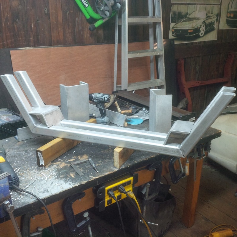
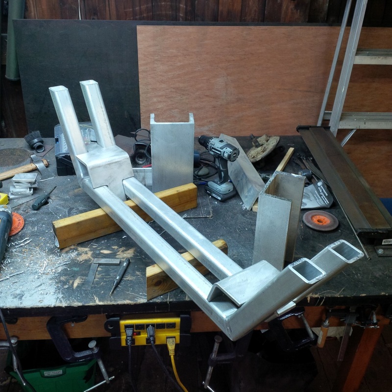
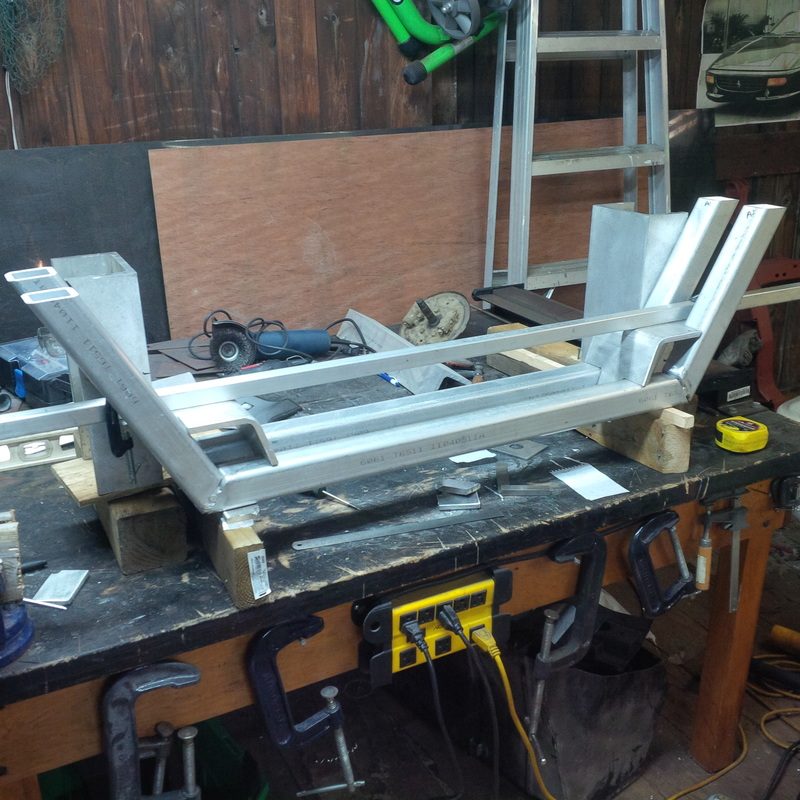
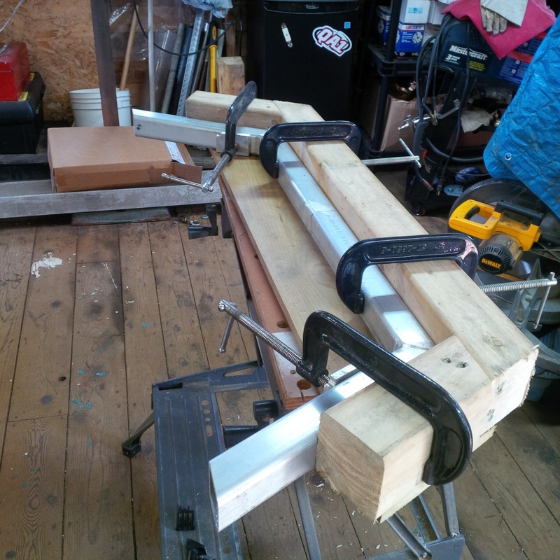
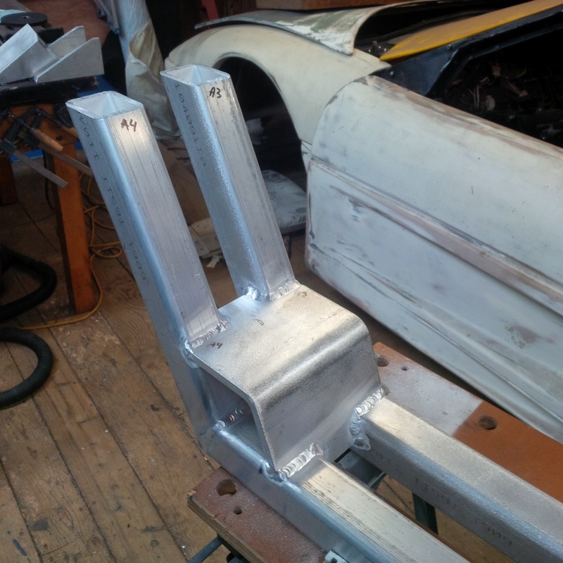
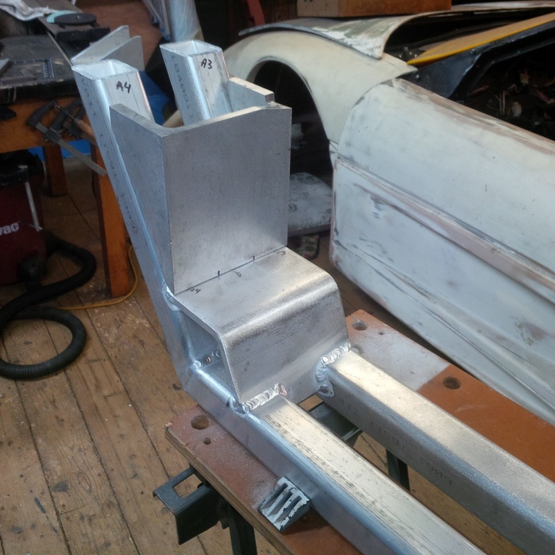
Ok, here is a long awaited project update. As you can see, I started fabricating the aluminum cross member as per my design with twin 2" x 2" x 1/4" square extrusions that angle upwards on the outside of the front lower chassis frame. The mounting flanges for the cross member are made from 3/8" plate that has been bent to form the lower mounting flange and tie the two frame members together. Originally, I made the angled cuts in the square tubing the tacked them together at the desired lengths and angles. However, it was very difficult to keep them at the desired shape once they were welded. After the first attempt, I was unhappy with the results so I added them to the scrap bin and started over. On the second attempted I built a more robust wooden jig to keep everything where I wanted. This worked well and I was able to fit both cross members in the jig at one time so I knew they would be as similar as possible.
Ok, here is a long awaited project update. As you can see, I started fabricating the aluminum cross member as per my design with twin 2" x 2" x 1/4" square extrusions that angle upwards on the outside of the front lower chassis frame. The mounting flanges for the cross member are made from 3/8" plate that has been bent to form the lower mounting flange and tie the two frame members together. Originally, I made the angled cuts in the square tubing the tacked them together at the desired lengths and angles. However, it was very difficult to keep them at the desired shape once they were welded. After the first attempt, I was unhappy with the results so I added them to the scrap bin and started over. On the second attempted I built a more robust wooden jig to keep everything where I wanted. This worked well and I was able to fit both cross members in the jig at one time so I knew they would be as similar as possible.
From here, I had the pieces tig welded at work together with the lower frame mounting flanges. The resulting cross member was straight and true and I was happy with the results at this stage.
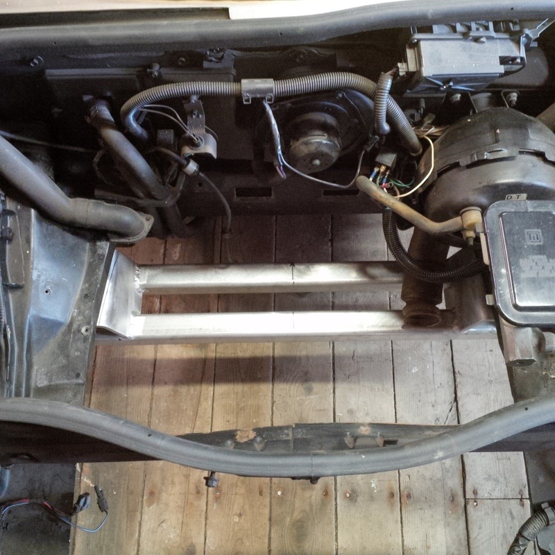
At this point, I can now mount the new cross member to the chassis. I used the stock cross member to get the location of the four holes that I then drilled in the upper surface of the lower mounting flange. Using the stock bolts, I secured the new cross member to the chassis. here is how it looks at this point. You'll notice that I removed the spar tire tub from the chassis prior to installing the cross member. This was to provide better access to the front end while I am working on it as well as eliminate the interference between the lower edge of the tub and the new cross member. The stock cross member actually jogs forward slightly to avoid interference. My new design cuts straight across the frame rails which is fine as I planned to redesign the tub to act as a front battery tray anyway.
|
|
After spending some time under the front of the chassis I realized that I could probably remove the stock lower control arm mount and the upper shock mount as they will not be used with my new front suspension design.

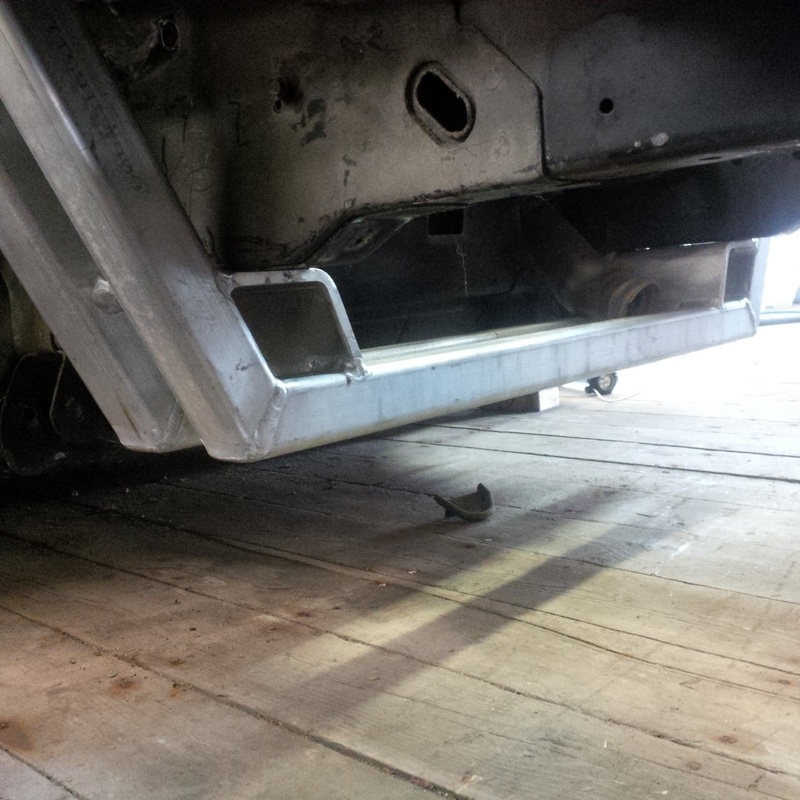
With the cross member in place, the next step is to fit the vertical flanges that will allow the cross member to bolt to the stock side mounting points on the outside of the front frame rails. This flange is cut from 6" x 3" x 3/8" aluminum channel. This is what one side looks like. It will be welded along its length to the two square tubes of the new cross member.
July 2 2016
While enjoying a relaxing day off, Happy Canada Day, I continued with the construction of the front cross member structure. As shown above, the next pieces to be fitted are the vertical upright flanges that will bolt the new cross member to the stock locations on the chassis. In all there are 10 stock bolt locations ( 5 per side) that secure the cross member to the chassis and I intend on using every one of them.
As often happens, I tend to modify my original design as I am building, usually to enable fabrication of difficult parts or just because I discover a more suitable design as I proceed. In this case, my original design had the vertical flange surface extend all the way down to the horizontal flange surface. While this looked fine on paper ( well, computer screen), it made a situation which would have very poor accessibility for proper welding. As the cross members proceed downward at an angle, the vertical flange thickness gets reduced to almost to zero, thus making a point inside the flange that would be impossible to weld. Since the vertical flange actually only touches the chassis frame rail at the top half of the flange, I decided to remove the lower portion of the vertical flange. Here is the resulting design with the change incorporated.

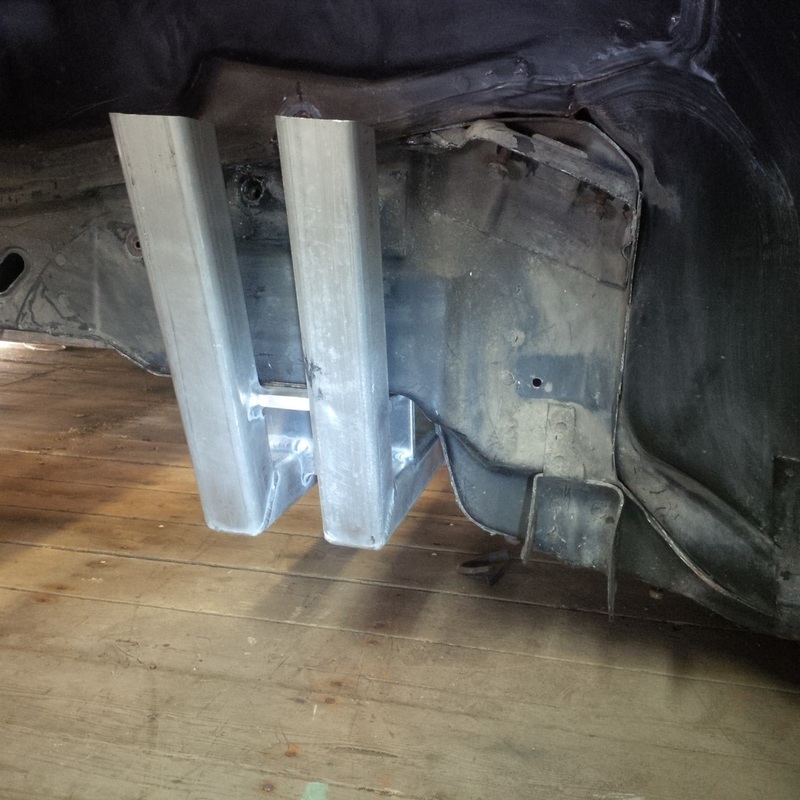
Here are the actual parts fabricated and held in place temporarily for a photo opportunity.

The next step is to fabricate the upper extended mounting flange. This is a single bolt mount and makes the total securing bolts 5 per side. I fabricated this from a section of the same 6" x 3" aluminum channel used for the lower part of the vertical mounting flange. Here is what it looks like precariously balanced for a photo.
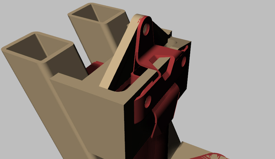
At this point, I should point out something that I have included in my design that is not apparent in the actual build. From my 3D model, with the new design overlaid on the stock cross member, you can see that I have modeled the two vertical flange mounting surfaces to be set back 1/8" from the stock location. I have also made the mounting holes in the horizontal mounting flange elongated in shape. This will allow me to shift the final cross member assembly side to side 1/8" so that I can tweek the transverse position when its all done. This will allow me to correct for slight errors that may occur during construction, should they be noticeable when the final body and wheels are on. I am not sure if this will be necessary but I thought it might be a nice option down the road. The resulting space between the front cross member and front frame rails will be taken up with suitable thickness delrin spacers.
Here is the design showing the new cross member and the stock cross member.
Here is the design showing the new cross member and the stock cross member.
|

|
You can see in this close up how the new mounting flanges ( tan color) are set back from the stock location ( red brown).
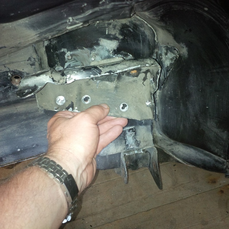
Back to working on the chassis tonight, I removed the drivers side and passenger side stock upper shock mount. This is just for cosmetic reasons as they don't really interfere with the new front suspension set up. Here is the drivers side. I'll spare you the image of the passenger side. It did not come out quite so easily. :(
I had planned on removing the stock lower control arm pivot. However, they are structurally much more integrated into the front frame rails so I will remove the protruding flanges but leave the body on the piece intact on the chassis.
Sept 25 2016_________________________________________________________________________________________
Wow, my first update since early July. Thanks for hanging in there. It was a busy summer with beautiful weather the past few months in Nova Scotia. With all the home projects completed, it's time to get back to the project that really matters ha-ha-ha.
Even though I haven't posted any updates in a while, I was periodically working on the front cross member, making the brackets and components required to allow the new aluminum front cross member to bolt up to the chassis. Along the way, I made a few small changes to the design to facilitate fabrication as well as make the whole assembly easier to bolt in while making sure the entire assembly was exactly where I wanted it. A few millimeters in the wrong direction could throw my whole alignment out of wack down the road.
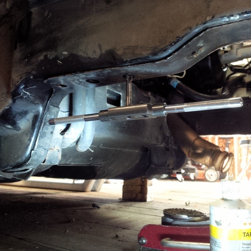
My first task this weekend was to tackle a little matter that I have been avoiding for a while. One of the stock bolts that secures the stock front cross member to the underside of the passenger side frame rail was sheared off flush with the frame. Odd thing is I don't remember breaking the bolt off when I removed the stock cross member a long time ago. Regardless, that hardened bolt needed to be removed. Of course it is on the underside of the frame rail so it meant getting in there with an angle drill first. After drilling the broken bolt out with successively larger drill bits and twisting an easy-out almost to the point of shattering, I realized that bolt was there for life. So I drilled and tapped what was left to take a new M10 x 1.5 bolt. I took extra care not to snap the tap off in the hole as this would have been an even larger problem to fix. It's a wonderful feeling to finally have that tap running all the way through the material and it's amazing how such a small achievement can give you such a great sense of accomplishment. :)
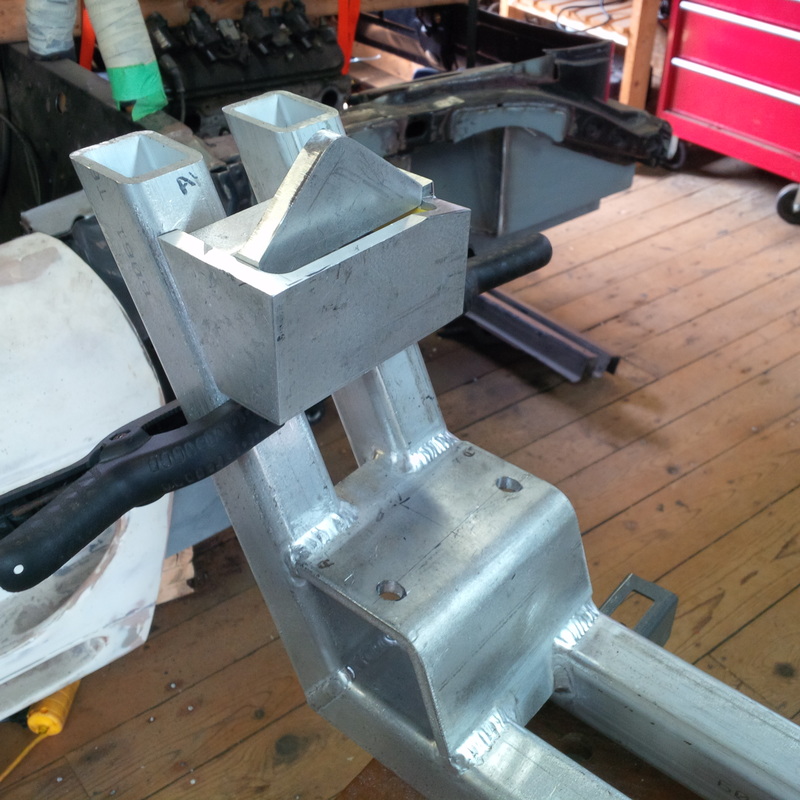
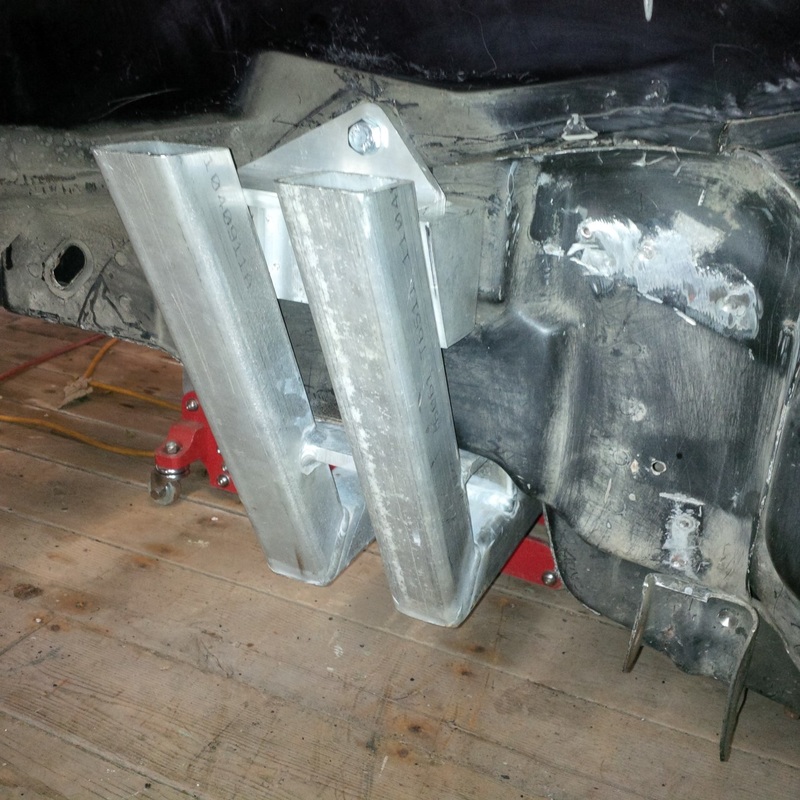
With this task complete, I was now able to put the new front cross member in place and hold it there with a jack while I bolt it in place on the chassis. I then added the remaining components that will be added to the cross member so that the whole assembly can utilize all 10 points of attachment like the stock cross member. You can see images of the components back in my July post. Here is what they look like bolted to the chassis. With all these parts fitted like I want them, I'll tack them all to the cross member prior to removing the entire assembly for final welding. This will help ensure that all the parts are located correctly so it will hopefully bolt back in place once welding is complete.
Oct 3 2016
By Dave
Good to see you back at work on the front cross member. You mentioned you're planning to tack weld it in situ, and complete the welding once removed. But since your chassis is the perfect jig, why not weld as much of it as practicable while the various parts are still bolted to the frame?
Response by Graham
Hi Dave. Sorry for the slow response to your post. You are 100% correct that the frame makes the perfect jig for holding the front cross member while its being welded. The main reason for removing it is to get access to all the edges. With the cross member in place, its very hard to get in the wheel well with two hands in front of you for TIG welding. And many of the edges to be welded will requiring rolling the cross member over to get on the back side and inside edges. I am hopeful that we can get enough good tacks on the assembly that it will be ok. The other thing in my favor is that the welding is concentrated just on the ends of the already fully welded cross member structure so any heat distortion will be concentrated at the outer ends. As well, while the parts look large in the photos, the actual components are surprisingly small relative to the over all cross member size so there won't be a huge amount of welding to do. My fingers are crossed. :)
