the rear frames
June 1 2014
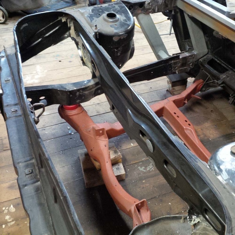
The Fiero chassis has an upper and lower frame rail that extends rearward from the firewall and forms the chassis which surrounds the engine bay and provides support for the rear struts. They are formed from a series of sheet metal stampings which are spot welded together. Typically on an older car such as a Fiero, these frame rails tend to rust out and create serious structural problems for the car. Luckily, my chassis is rust free so I have a sound foundation on which to build my car around. Unfortunately, the stock frames don't quite meet the needs of my project car. The main issue is the location of the stock lower frame rails. As you can see from my drawings, they angle inward as they proceed rearward. This is fine for the stock strut towers that connect the upper frame rail and the lower frame rail. But because I plan to widen the rear track of my car by 8" to suit the 355 body, I'll need to move my strut towers outward 4" per side. This would mean that the lower frame rail would no longer provide any structural support and thus be useless. Here are a few images of the stock frame rails.
The Fiero chassis has an upper and lower frame rail that extends rearward from the firewall and forms the chassis which surrounds the engine bay and provides support for the rear struts. They are formed from a series of sheet metal stampings which are spot welded together. Typically on an older car such as a Fiero, these frame rails tend to rust out and create serious structural problems for the car. Luckily, my chassis is rust free so I have a sound foundation on which to build my car around. Unfortunately, the stock frames don't quite meet the needs of my project car. The main issue is the location of the stock lower frame rails. As you can see from my drawings, they angle inward as they proceed rearward. This is fine for the stock strut towers that connect the upper frame rail and the lower frame rail. But because I plan to widen the rear track of my car by 8" to suit the 355 body, I'll need to move my strut towers outward 4" per side. This would mean that the lower frame rail would no longer provide any structural support and thus be useless. Here are a few images of the stock frame rails.
|
|

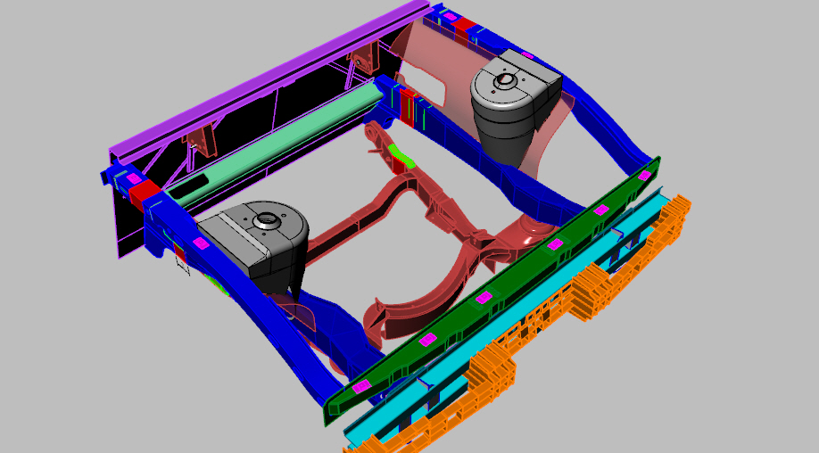
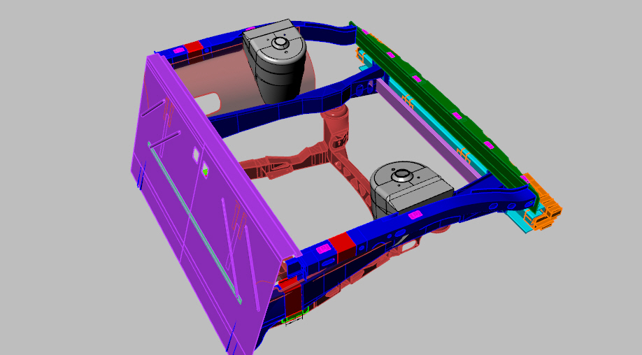
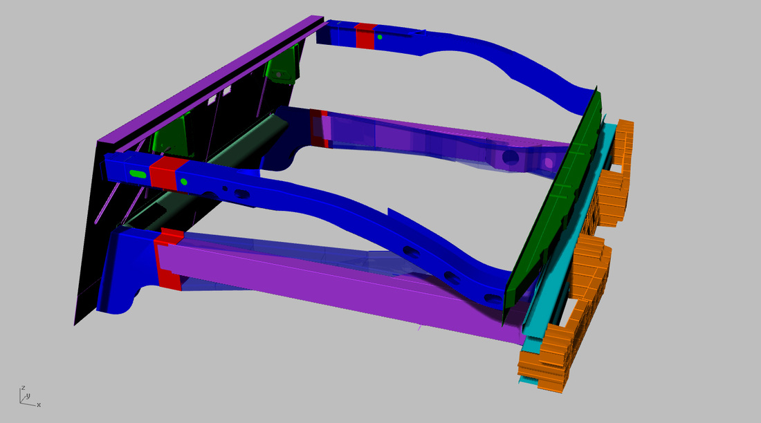
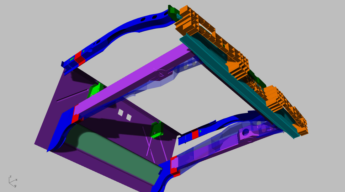
Here is how the new frame rails (purple) will look with the stock lower frame rails (blue) ghosted for reference. I removed the strut towers for clarity. You can see how the new rails will project straight back from the firewall. This will allow them to be perfectly positioned for the new strut towers later on. I design the new lower rails with a widen section to correspond to the engine cradle rear mounting point, in a fashion similar to the stock lower frame rails.
|
|

July 21 2014
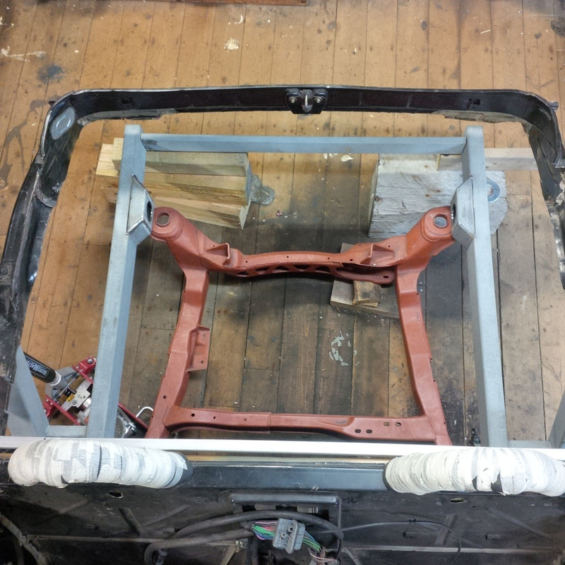
Here is the chassis with the stock rear frame rails in place but the trunk compartment removed to expose the lower rails to be removed.
Here is the chassis with the stock rear frame rails in place but the trunk compartment removed to expose the lower rails to be removed.
Sept 7 2014
The next step was to remove the strut towers and then cut the lower frame rails off at the point where the original 3" chassis stretch had been completed. The will allow me to secure the forward end of the new frame rails to the reinforced frame rail insert that I had installed during the original chassis stretch.
The next step was to remove the strut towers and then cut the lower frame rails off at the point where the original 3" chassis stretch had been completed. The will allow me to secure the forward end of the new frame rails to the reinforced frame rail insert that I had installed during the original chassis stretch.

|
|
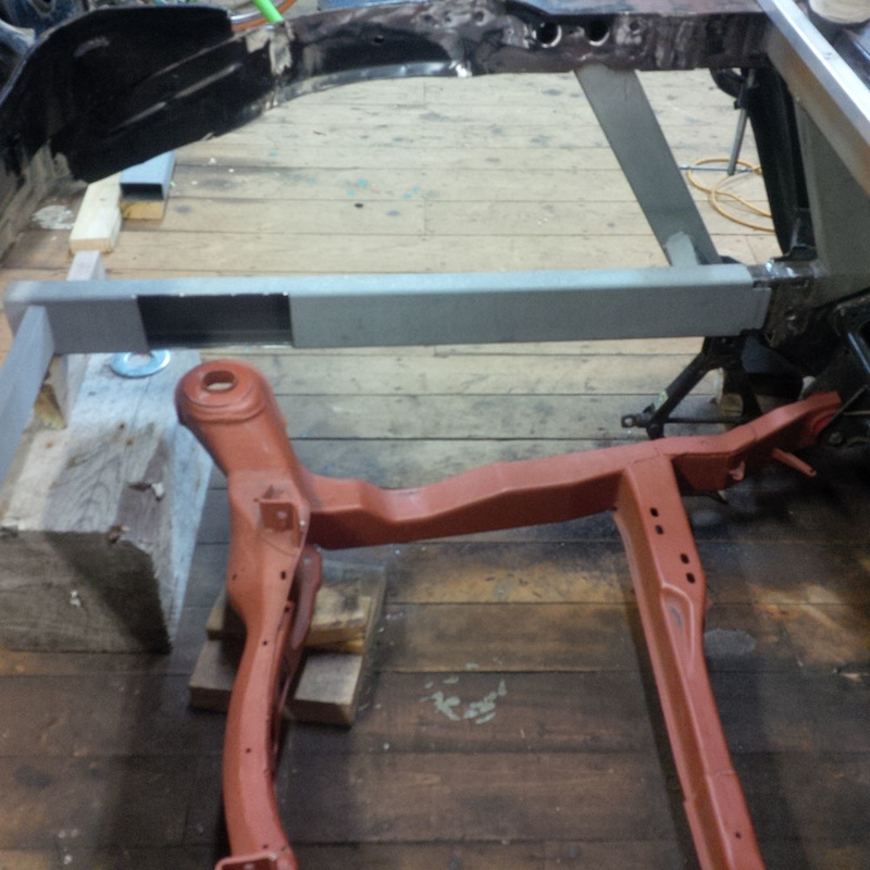
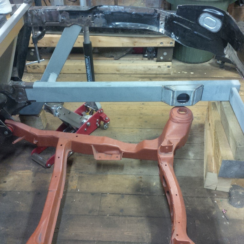
My new lower frame rails will be fabricated from 4" x 2" x 1/8" HSS and it will slip over the remaining insert to provide a solid point of attachment for welding. I installed a temporary transverse frame rail at the rear end of the new rails to help keep everything straight and square during fabrication. This transverse frame is fabricated from 3 x 1" x 1/8" HSS.
Oct 15 2014
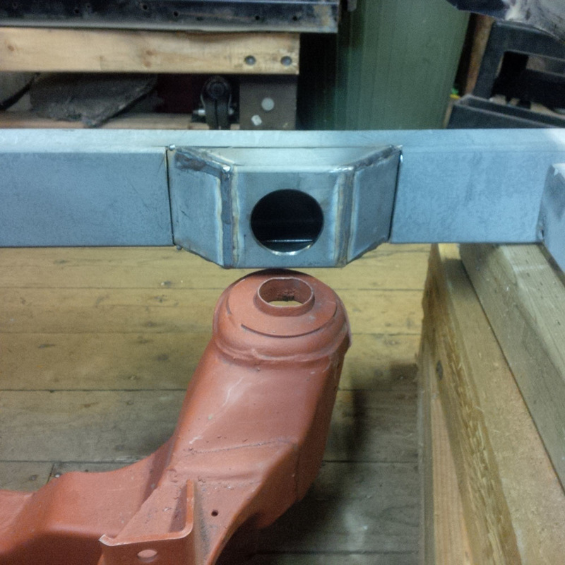
With the basic straight rails cut and mocked up, I fabricated the bulge on the inside surface of each rail to form the attachment point for the new engine cradle I will be designing and building. The bulges in the rails were fabricated from the same stock as the rails themselves. I added an access hole on the inside face to allow access to the securing bolt for the rear poly bushing on the new engine cradle.
With the basic straight rails cut and mocked up, I fabricated the bulge on the inside surface of each rail to form the attachment point for the new engine cradle I will be designing and building. The bulges in the rails were fabricated from the same stock as the rails themselves. I added an access hole on the inside face to allow access to the securing bolt for the rear poly bushing on the new engine cradle.
|
|
On the underside of the frame rail bulge, I welded a 4" diameter flat washer to create a flat surface for the rear cradle bushing to lay against.
With the frame rails all welded up and secured to the chassis, the next step is to build the new strut towers and plate in the engine bay between the upper and lower frame rails on each side of the chassis.
With the frame rails all welded up and secured to the chassis, the next step is to build the new strut towers and plate in the engine bay between the upper and lower frame rails on each side of the chassis.
July 16 2017
Holy smokes. It's been almost 3 years since I left this part of the project. When I left off, I had fitted a temporary transverse frame made from 3" x 1" square tubing between the new lower longitudinal chassis frames. This was used just to keep everything straight and square and in place during welding ( see photos above). At the time, I knew that the frame would likely be in the way of my future 01E gearbox. Well, now that my gearbox has arrived, it is time to finish the chassis.
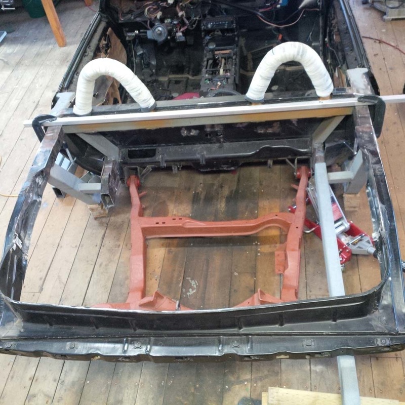
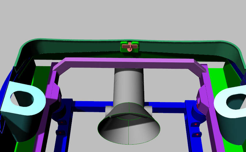
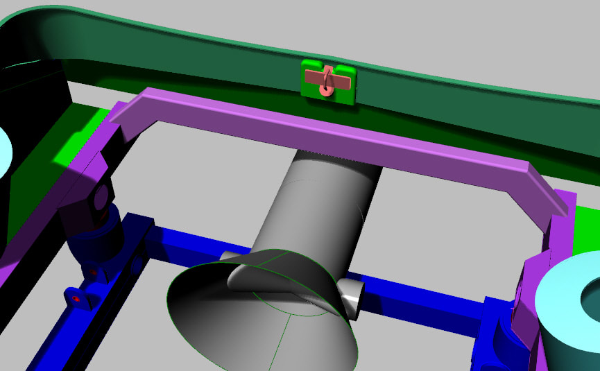
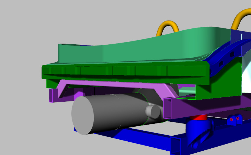
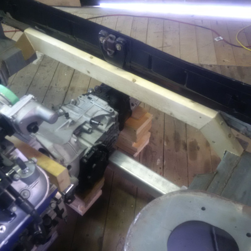
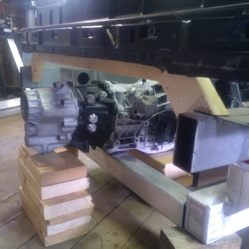
I decided to build the new transverse frame with 3" x 1-1/2" x 1/8" rectangular tubing. Apart from what remains of the original rear trunk sheet metal, there is very little transverse structure connecting the left and right side of the chassis that extends rearward of the firewall. For this reason, I decided to make sure this new transverse frame is adequately substantial to resist the chassis twisting under load. In order to clear the top of the gearbox, I raised the location of the frame and then angle the ends downward to meet up with the lower longitudinal frame rails. I located the new frame as far rearward as possible so that it is actually tucked in under the original engine latch striker plate. I have no idea if this part of the OEM engine deck latch will be used in the future with the 355 body but I figured I leave it in place until such time as I make a final decision on that matter.
I am also keeping in mind that eventually I will need something secure to hang the future exhaust system from and this transverse frame will hopefully be more than adequate.
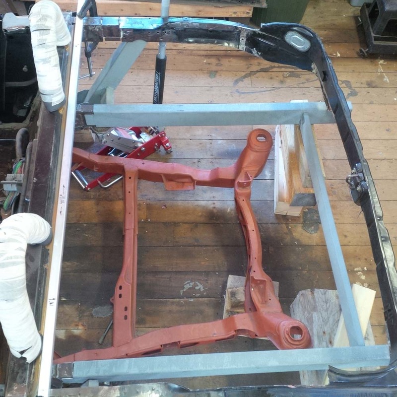
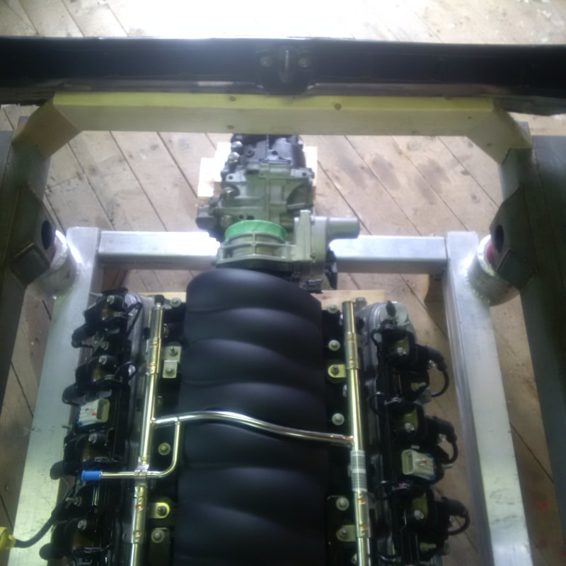
Here are a few images of the new transverse frame from my 3D chassis model and a couple matching photos showing a similarly sized wooden frame I mocked up with some spare lumber I had laying around. It's always nice to visually confirm an idea with cheap easy material before you start cutting and welding.
|
|
July 26 2017
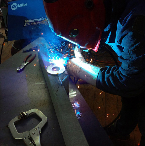
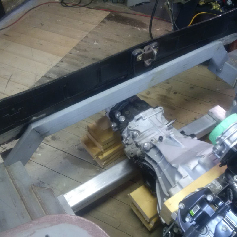
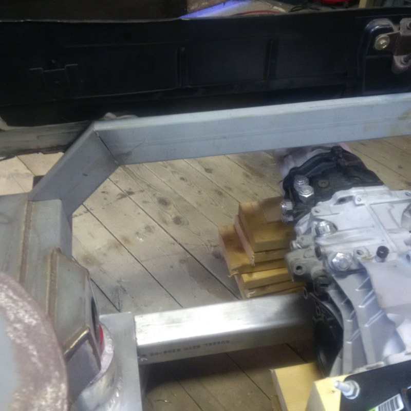
I finally got around to fabricating the rear transverse frame. I decided to use 3" x 1" x 1/8" rectangular tubing as opposed to the 3" x 1-1/2" x 1/8" I stated above. The 1" seemed to tuck in better under the stock Fiero striker plate structure and is still more than strong enough to stiffen up the rear ends of the lower longitudinal frames. Tacked together, the entire frame comes out for full welding prior to welding it in place on the chassis.
I finally got around to fabricating the rear transverse frame. I decided to use 3" x 1" x 1/8" rectangular tubing as opposed to the 3" x 1-1/2" x 1/8" I stated above. The 1" seemed to tuck in better under the stock Fiero striker plate structure and is still more than strong enough to stiffen up the rear ends of the lower longitudinal frames. Tacked together, the entire frame comes out for full welding prior to welding it in place on the chassis.
|
|
