Transmission Mounts
August 12 2017
I figured since I have been breaking down the topics into discrete subjects, I may as well separate the transmission mount details from the engine mounts. So here are the transmission mounts I have ordered from Energy Suspension.
I figured since I have been breaking down the topics into discrete subjects, I may as well separate the transmission mount details from the engine mounts. So here are the transmission mounts I have ordered from Energy Suspension.
|
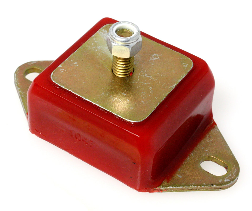
These are actually Jeep engine mounts, part # 2.1102, designed for early model CJ's and 6 cylinder Wagoneers. As I mentioned, I chose these units mainly because of their geometry which seems to fit my engine cradle structure well.
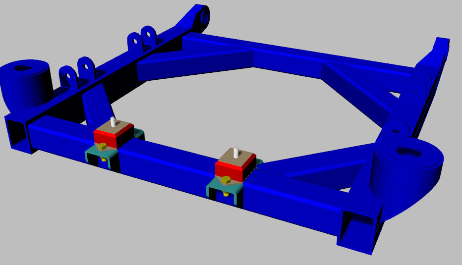
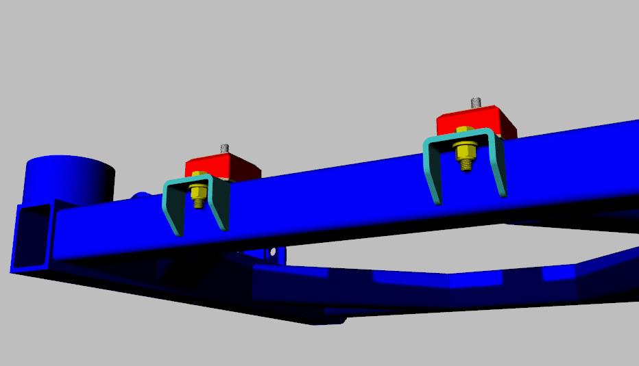
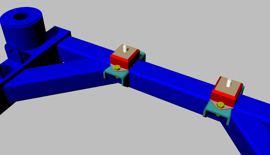
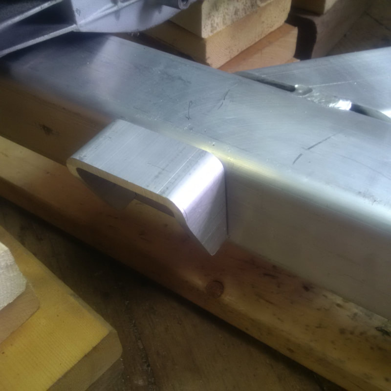
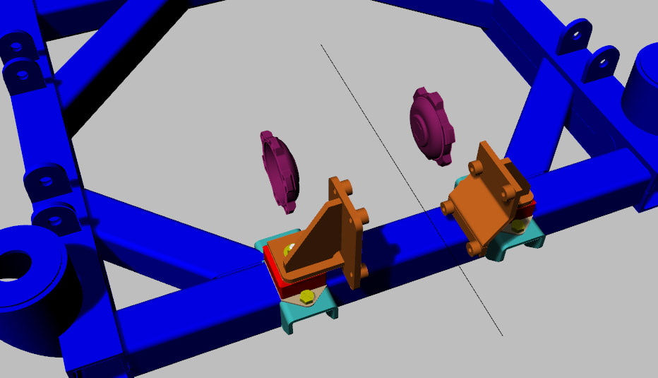
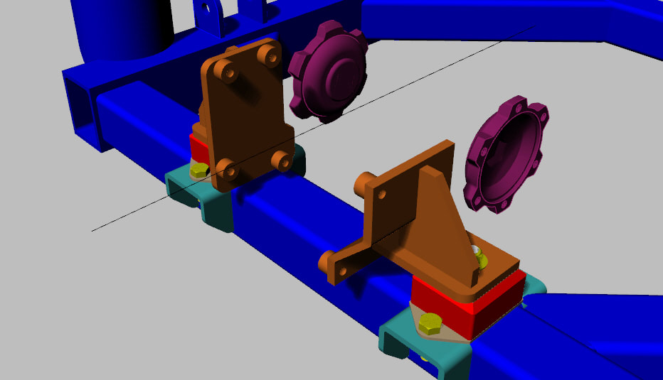
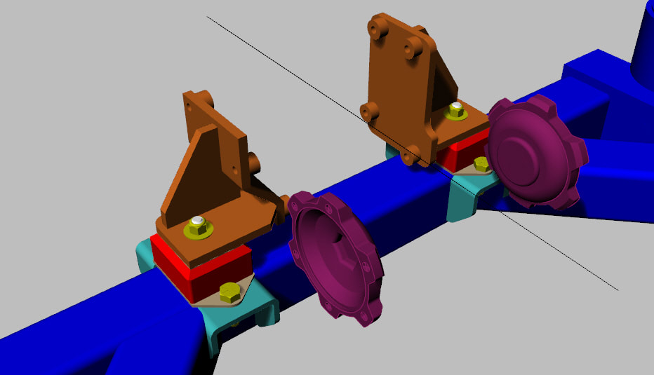
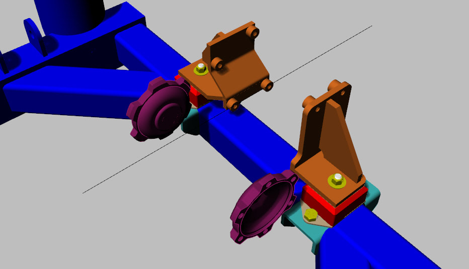
Here are a few images from my 3D model showing the mounts in their approximate location on the cradle. I am going to fabricate the mounting gussets from the same 3" x 3" x 1/4" square tubing as the cradle and just cut them down to suit my application. |
|
|
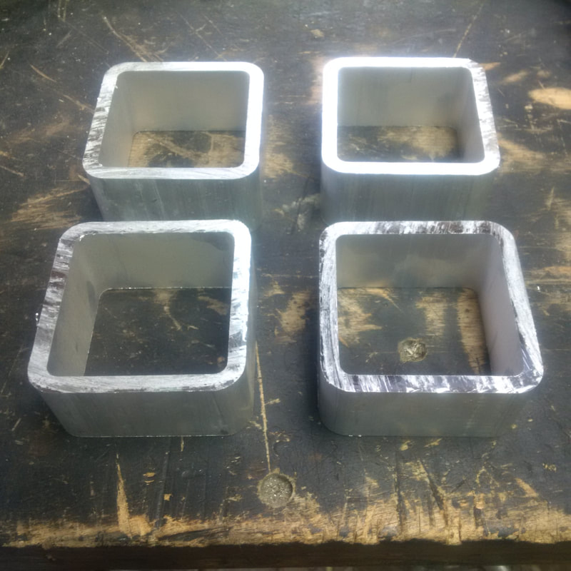
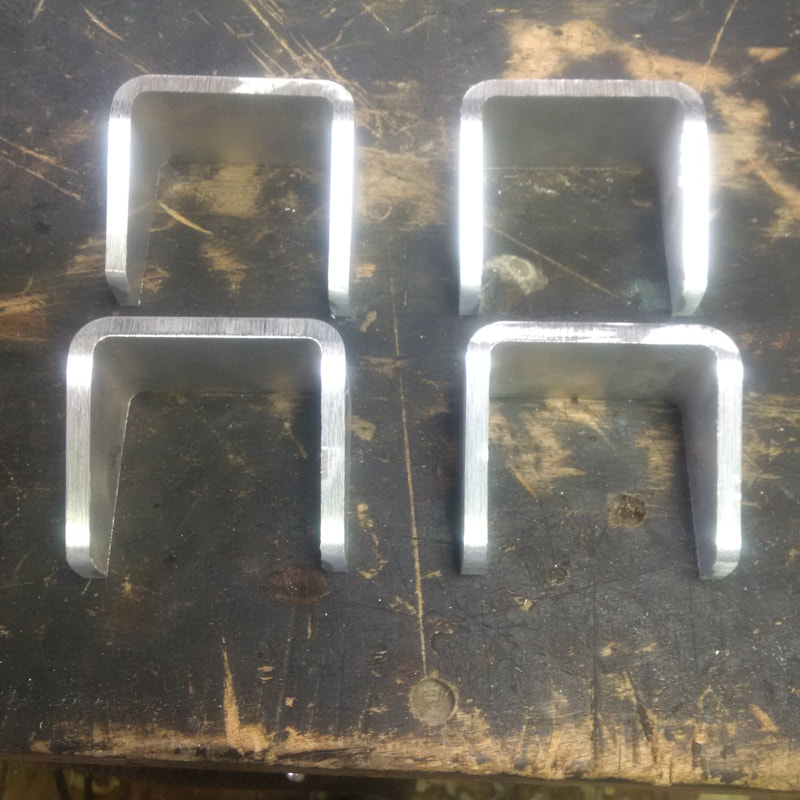
Here are the mounting gussets, starting out as some 3" x 3" x 1/4" tubing. A little cutting and sanding and they are ready to be tacked in place. I'll wait until my mounts actually arrive before any welding is done.
|
|
August 19 2017
Here are a few images of the transmission mounts I have designed to work with the above noted poly mounts. The 01E transmission mounting bolt locations seem to be completely random with regard to one another as well as in no way symmetrical from one side to the other. They are certainly going to be a challenge to fabricate.
|
|
|
|
October 28 2017
Here are the transmission mounts held in position temporarily on the recently extended cradle. Like the engine mounts, they will be welded in position once I have the engine and transmission bolted together and sitting on the cradle. I may still have to notch the top of the transverse frame between the transmission mounts to provide a little more clearance with the transmission case underside.

