The Drive Line
August 6 2017
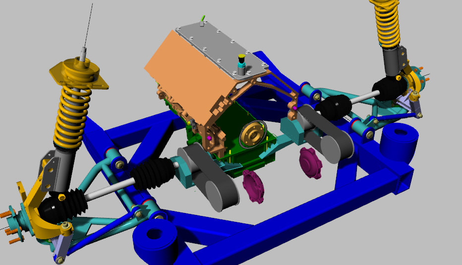
Now that I am at the point where I can set the engine and transmission on the engine cradle, I get my first glimpse of what the drive line is roughly going to look like. At this point, the engine is as far forward as it can go up behind the firewall and the transmission is located behind the engine bell housing with a 1-1/2" gap for the future adapter plate that I will either purchase or have machined to suit my installation. I have not finished the 3D model of the LS3 but I have enough done to locate the bell housing. I have not finished much of the 3D model of the 01E transmission either but I have modeled the two drive shaft output flanges and located them relative to the engine. From here, I am able to model the drive shafts based roughly on Fiero stock inner and outer CV joints. Again, while the dimensions and equipment locations are not exact, I can get a pretty good idea of what I am in for with regard to the drive shafts. Here are a few images from the 3D model and as you can see, the drive shaft is going to be running at an angle of around 25 degrees. This is excessive in my opinion although there are plenty of articles on the web that say this is still acceptable. I will continue to research this topic and develop a plan of action.
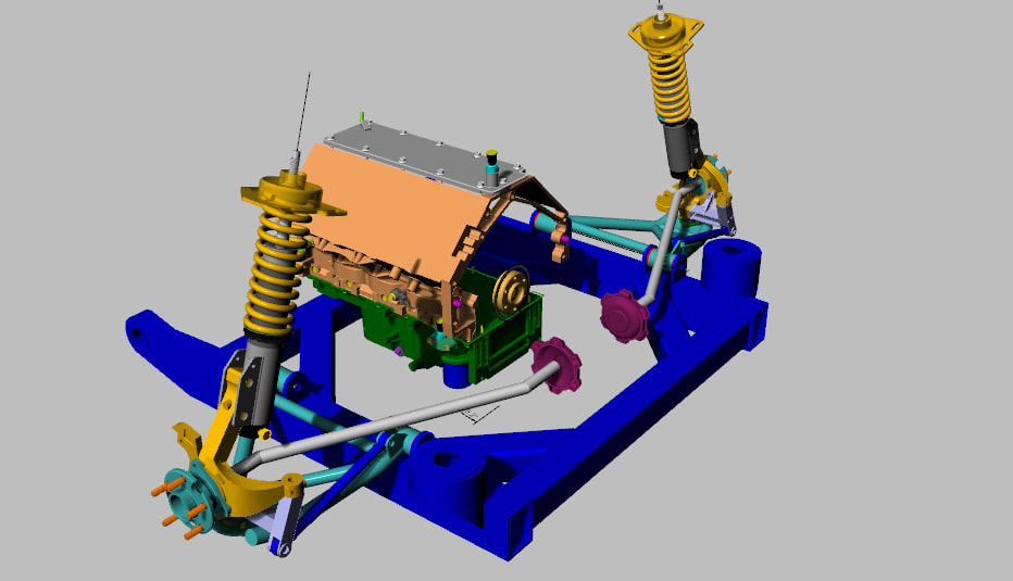
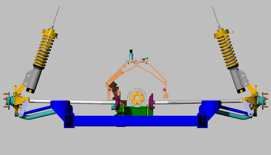
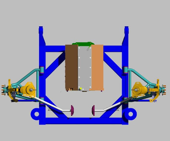
You'll notice that the output flanges of the 01E are offset towards the drivers side. The means that the passenger side shaft will be a little longer and also at a slightly less angle of attack. The main concern is when you look at the shaft line as it passes over the rear control arms. As I have always suspected, there is going to be significant interference between the drive shafts and the rear control arms on both sides of the car. Here is what the drivers side looks like.
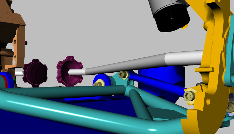
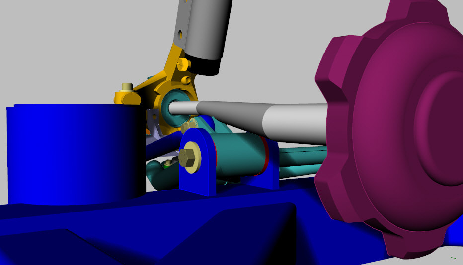
One possible solution for this problem would be to transpose the drive shafts forward from the transmission so that they are in line with the rear spindles, thus eliminating the possibility of interference between the drive shafts and the rear control arms. The solution I am working on involves the use of toothed drive belts and corresponding toothed sheaves. More to come on this topic, but for now, here are a couple images of a VERY preliminary driveline I have been working on in the back of my mind.