Engine Mounts
May 14 2017
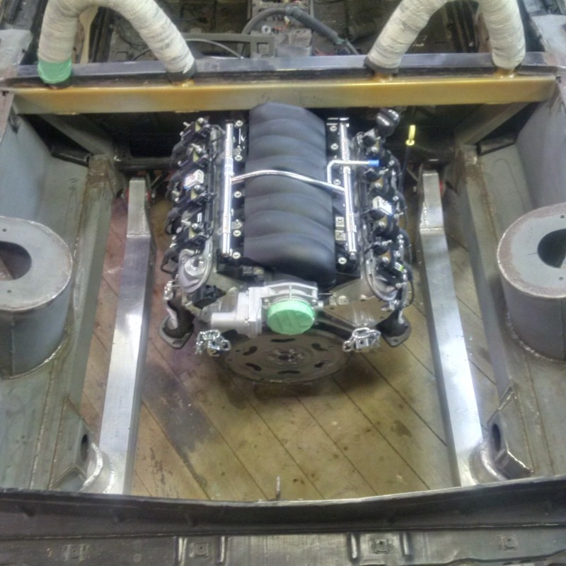
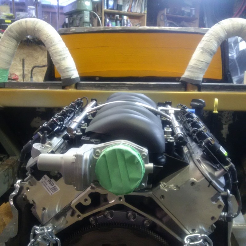
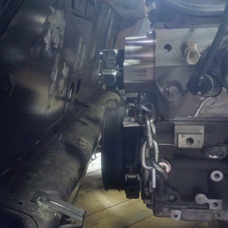
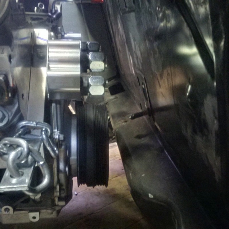
With the intake manifold reversed, it is time to place the engine in the engine bay and locate it in relation to the fire wall. Here are a couple pictures of the engine in place with the engine harmonic balancer approx 1" from the firewall and the height set at 5" between the underside of the oil pan and the floor. This also gives me just enough room on top of the intake manifold for the future engine bonnet.
|
|
|
|
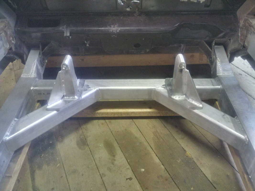
Once the engine was located in the engine bay, I installed the aluminum engine cradle. You may recall from the Chassis / Engine Cradle section, that I only built the two main longitudinal engine cradle rails and then connected them with a couple of temporary transverse rails. The reason for this was that without having the engine at that time, I had no idea where the transverse frame members would have to be located to clear the oil pan and the gearbox. At this time, I still don't have the gearbox so I will focus on the forward transverse frame. This is fine for now as the forward engine mounts are going to be located in relation to this frame.
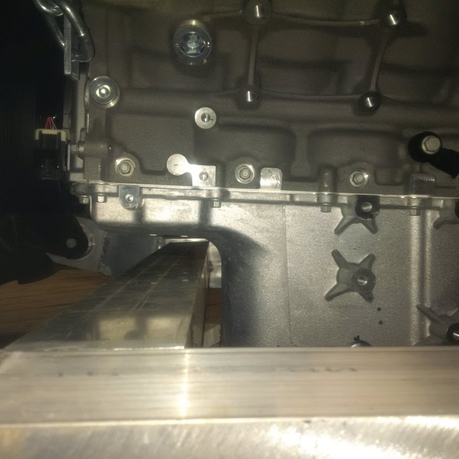
I removed the two transverse engine cradle frames as neither were going to be in the correct position. Looking at the forward transverse frame, the oil pan of the LS3 steps up in the front and at first glance, this should allow plenty of room for me to pass a structurally substantial transverse engine cradle frame which will eventually support the front left and right engine mounts. Here is a pic showing a temporary aluminum 2 x 4 passing in front of the oil pan. As you can see, there is plenty of room. I will detail the actual engine cradle construction in the Chassis / Engine Cradle section and then detail the engine mounts and supporting structure here.
I removed the two transverse engine cradle frames as neither were going to be in the correct position. Looking at the forward transverse frame, the oil pan of the LS3 steps up in the front and at first glance, this should allow plenty of room for me to pass a structurally substantial transverse engine cradle frame which will eventually support the front left and right engine mounts. Here is a pic showing a temporary aluminum 2 x 4 passing in front of the oil pan. As you can see, there is plenty of room. I will detail the actual engine cradle construction in the Chassis / Engine Cradle section and then detail the engine mounts and supporting structure here.
|
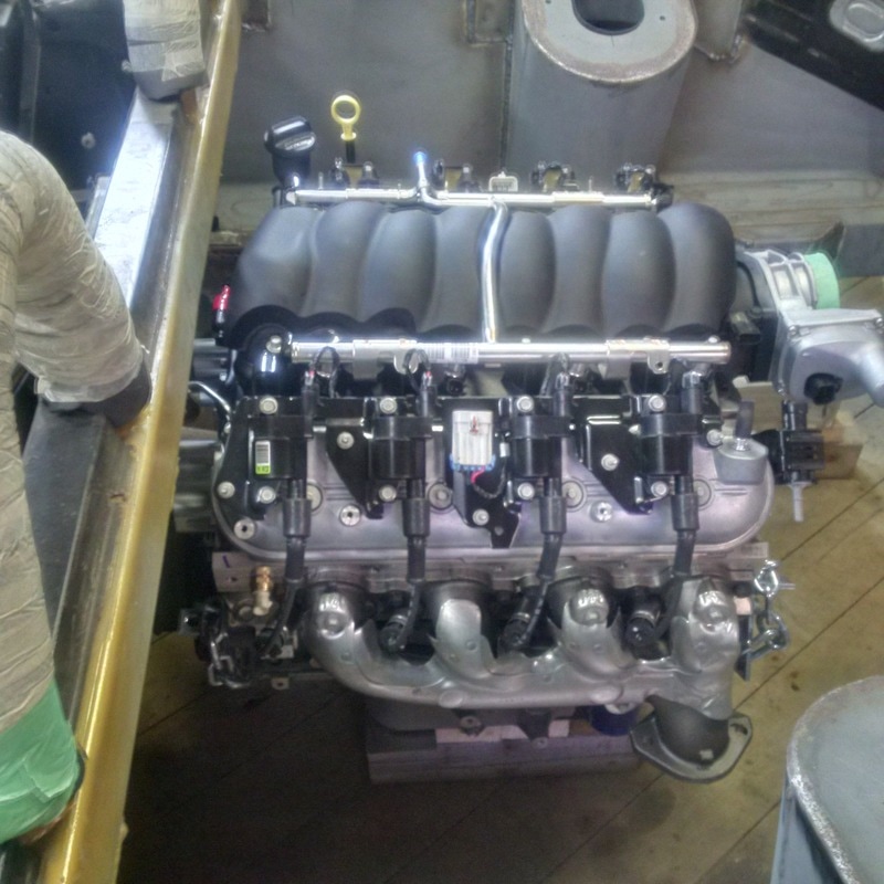
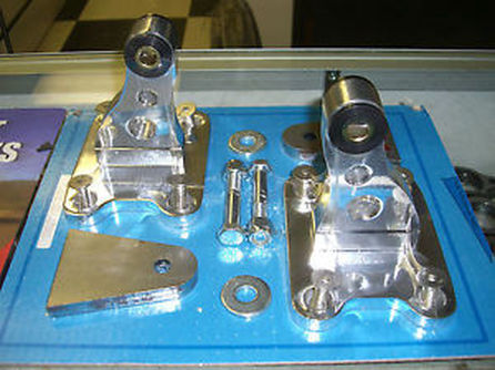
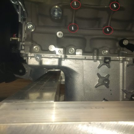
There are many different aftermarket mounts for the LS3. These shiny aluminum pieces caught my eye. They are designed to bolt on at the four points circled in red.
|
|
August 9 2017
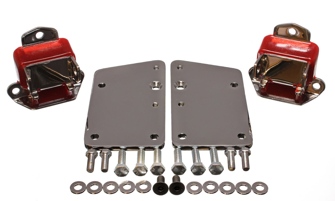
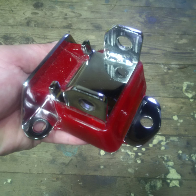
After a fairly extensive search for engine and transmission mounts, I settled on units from Energy Suspension. The LS3 engine mounts come with an adapter plate which bolts to the block and shifts the mounts farther forward than the stock mounts. These units are red polyurethane like all the suspension bushings I have been using around the chassis. These pieces are also chrome so they should look good on the engine.
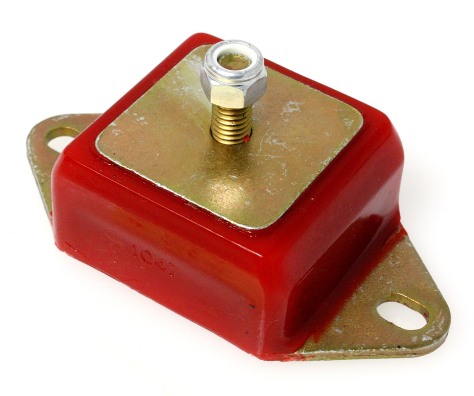
For the transmission mounts, I decided on a set of Jeep engine mounts because they had the dimensions that I needed to fit my engine cradle and they will work well with the mounting brackets I have been designing for the Audi 01E transmission ( ie: two base mounts and a single stud on top). They are also red polyurethane but unfortunately don't come with a chrome finish. Its kind of funny that the image of the mount on the Energy Suspension website looks like they are used pieces. Hopefully mine are new. :)
|
Once the mounts arrive, I will model them in 3D and finalize the rest of the mounting structure for the engine cradle and show you what I have come up with.
|
August 22 2017
The engine mounts arrived today and they are pretty much like the above image. I bought the chrome units just because they will look good against the aluminum block.
The engine mounts arrived today and they are pretty much like the above image. I bought the chrome units just because they will look good against the aluminum block.
|
|
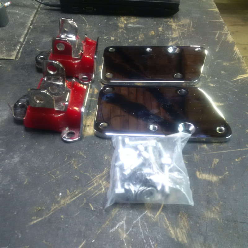
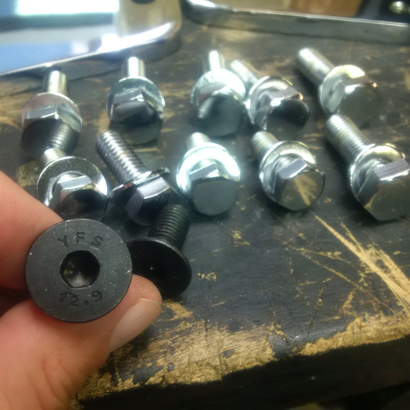
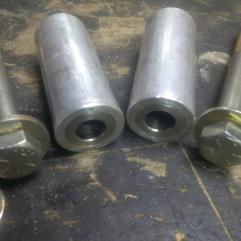
You may notice that in the image off the Energy Suspension website, the bolts are rated at 10.9 and the two countersunk bolts are rated at 12.9. However, you will notice in the photo below that the bolts supplied are chromed and polished but there is no rating markings. The two black counter sunk bolts still have their 12.9 rating though. I don't think the rating marking would be removed so I am a little skeptical as to whether these bolts are actually high strength or not. I'll use them for now to mock up the mounts and I'll contact the supplier regarding the supplied hardware. Regardless, I'll probably swap them all out for 12.9 hardened bolts just for piece of mind.
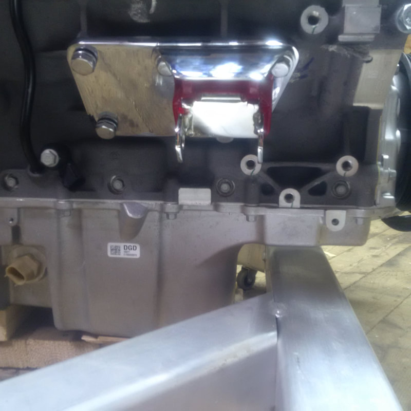
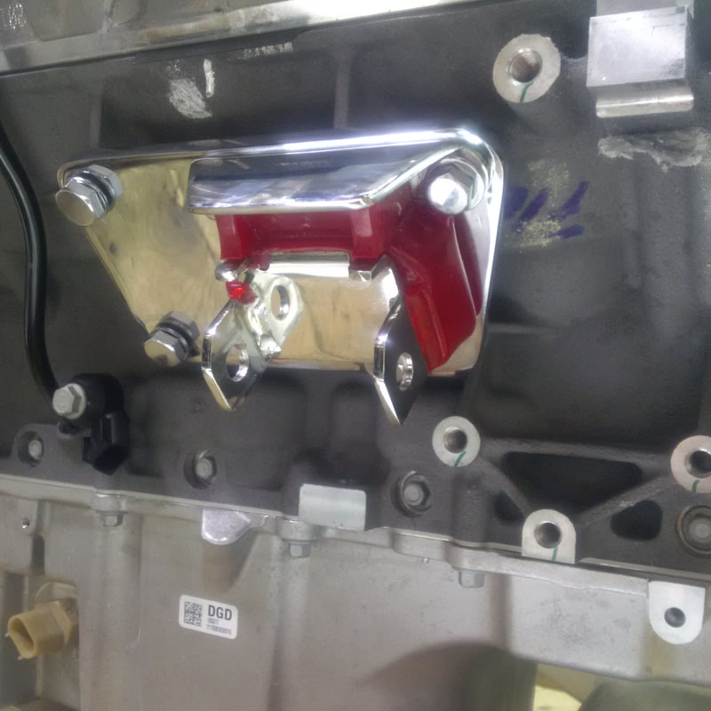
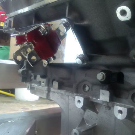
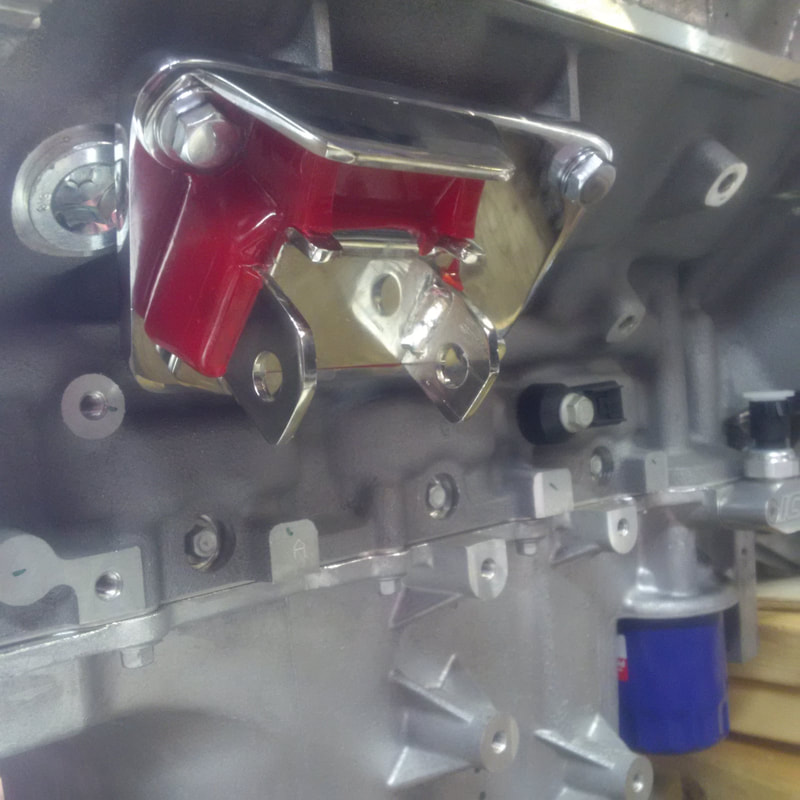
Here is the mount fitted to the passenger side of the engine. You can see that the adapter plate shifts the mount a few inches forward from the stock LS3 location and this puts it in line perfect with the cross brace of the engine cradle. I'll design the rest of the extended mount now that the actual flex mount is fitted to the block.
|
|
August 25 2017
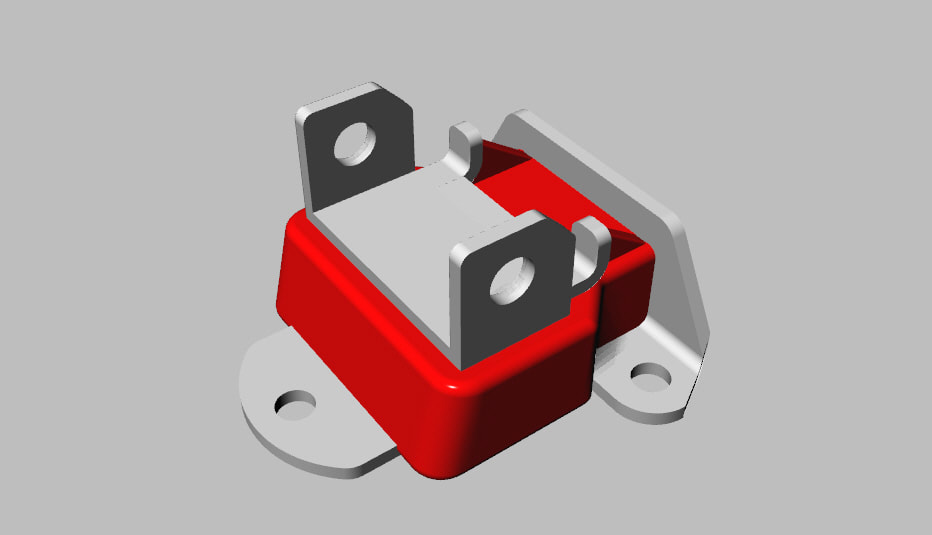
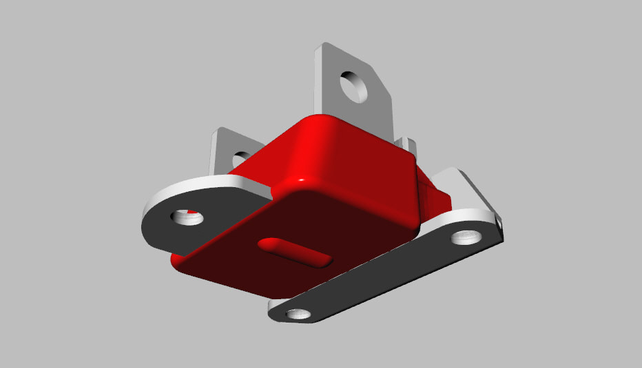
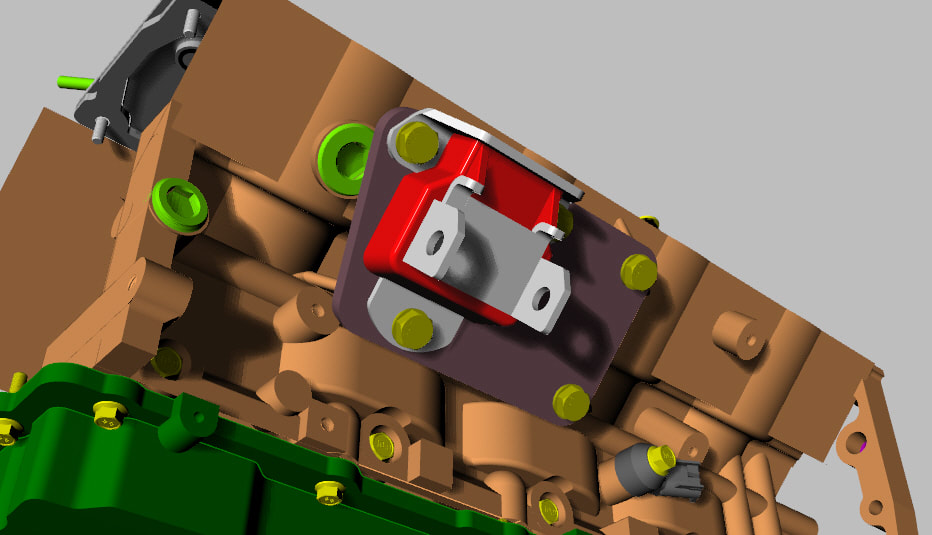
Here is my computer model of the engine mounts. I'll complete the LS3 mounting plates and then add them all to the engine 3D model.
Here is my computer model of the engine mounts. I'll complete the LS3 mounting plates and then add them all to the engine 3D model.
|
|
|
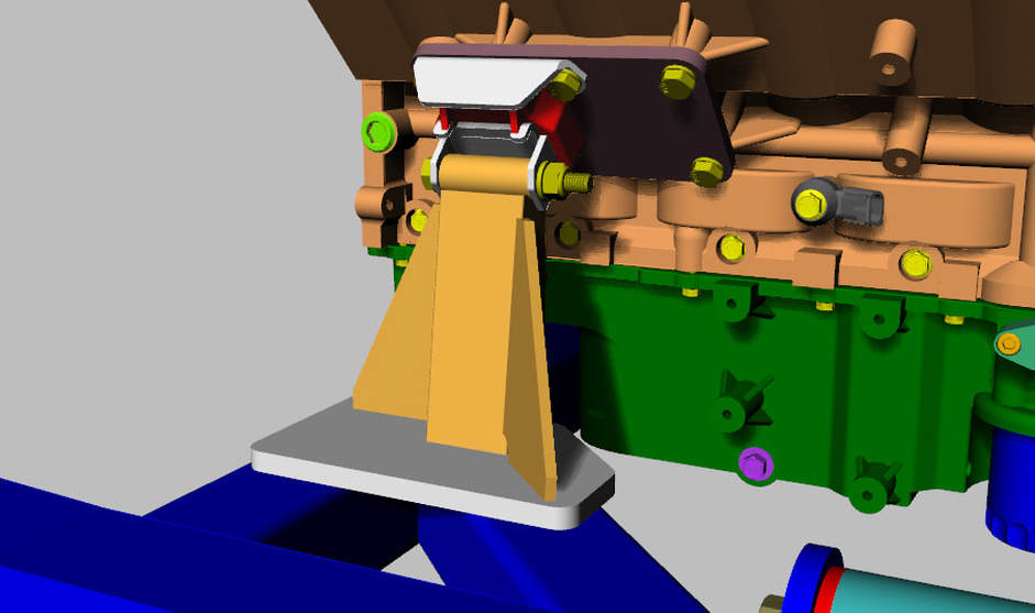
August 27 2017 Here is my computer model of the engine mounts on the LS3 engine 3D model. 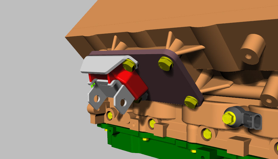
|
|
|
|
August 29 2017
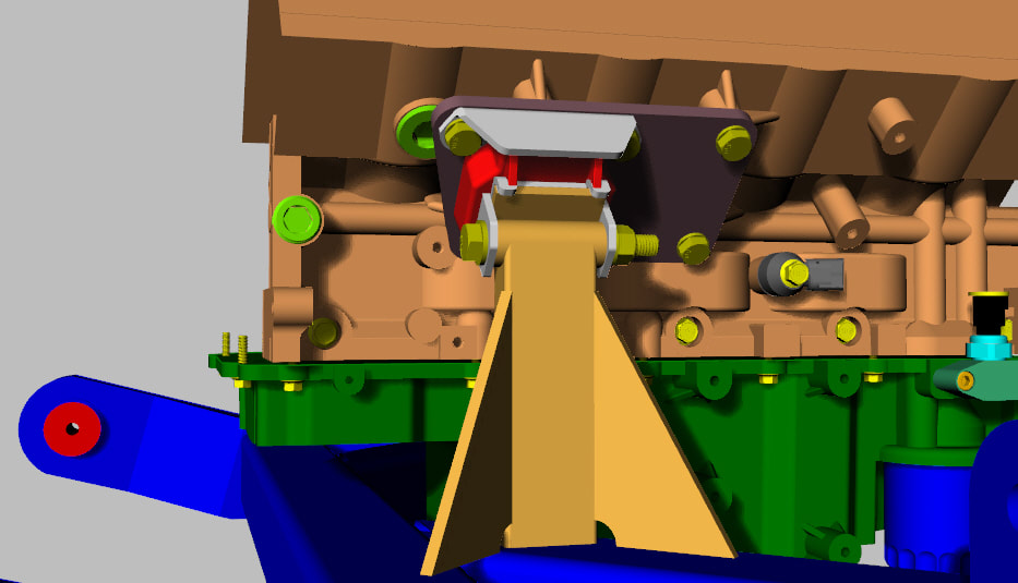
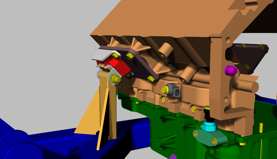
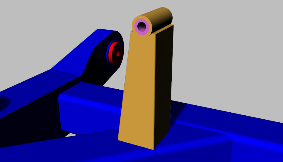
Here is my first kick at the engine mount support design. The set up will be fabricated from aluminum with the center mounting bolt hole being fitted with stainless steel bushings to stop the bolt from wearing through the aluminum support. I'll detail the construction once I finalize the drawing.
Here is my first kick at the engine mount support design. The set up will be fabricated from aluminum with the center mounting bolt hole being fitted with stainless steel bushings to stop the bolt from wearing through the aluminum support. I'll detail the construction once I finalize the drawing.
Sept 1 2017
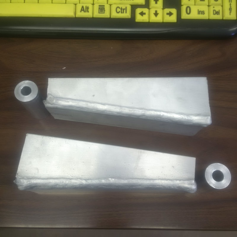
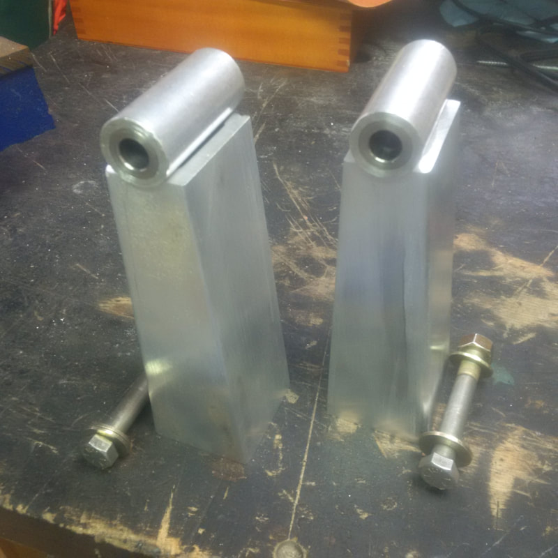
It's a little quiet here at work this afternoon before the long weekend so I decided to pop out to the aluminum shop and fab up a couple engine mount supports. My design above has them shown as 2" x 1" x 1/4" rectangular tubing. However, looking at our inventory of aluminum extrusions, I decided to make the supports out of 2" x 2" x 1/4" angles and then trim them back on the sides to form structure that has a 2" x 1" top and a 2" x 2" base. I made them a little extra long so I can trim the base as well as form the top to take the 1" diameter cylinder at the top. I bored the 1" round stock to take the 7/16" engine mount bolt for now but later I will bore the hole over size to take some stainless steel bushings. The supports are welded with an extra pass and I will sand the corners back to give the supports radius corners on all 4 sides.
It's a little quiet here at work this afternoon before the long weekend so I decided to pop out to the aluminum shop and fab up a couple engine mount supports. My design above has them shown as 2" x 1" x 1/4" rectangular tubing. However, looking at our inventory of aluminum extrusions, I decided to make the supports out of 2" x 2" x 1/4" angles and then trim them back on the sides to form structure that has a 2" x 1" top and a 2" x 2" base. I made them a little extra long so I can trim the base as well as form the top to take the 1" diameter cylinder at the top. I bored the 1" round stock to take the 7/16" engine mount bolt for now but later I will bore the hole over size to take some stainless steel bushings. The supports are welded with an extra pass and I will sand the corners back to give the supports radius corners on all 4 sides.

|
|
Sept 2 2017
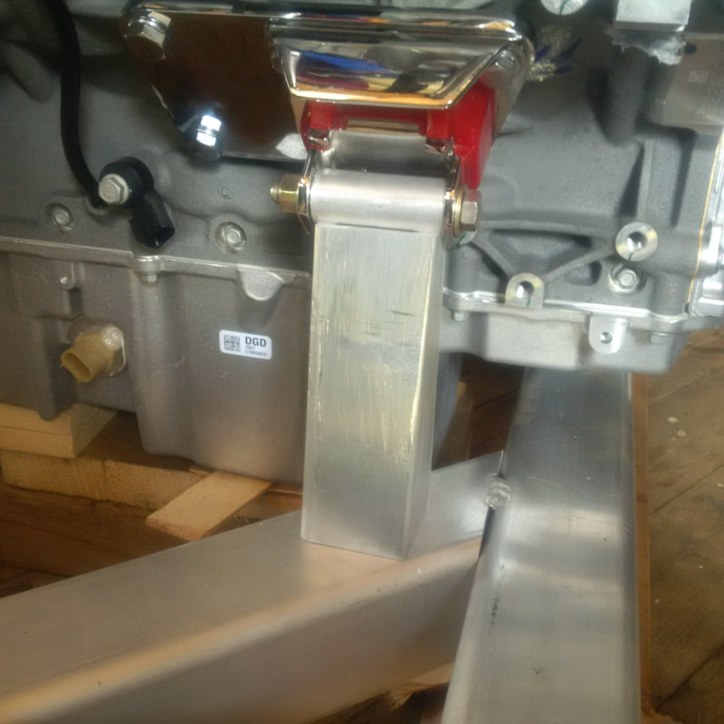
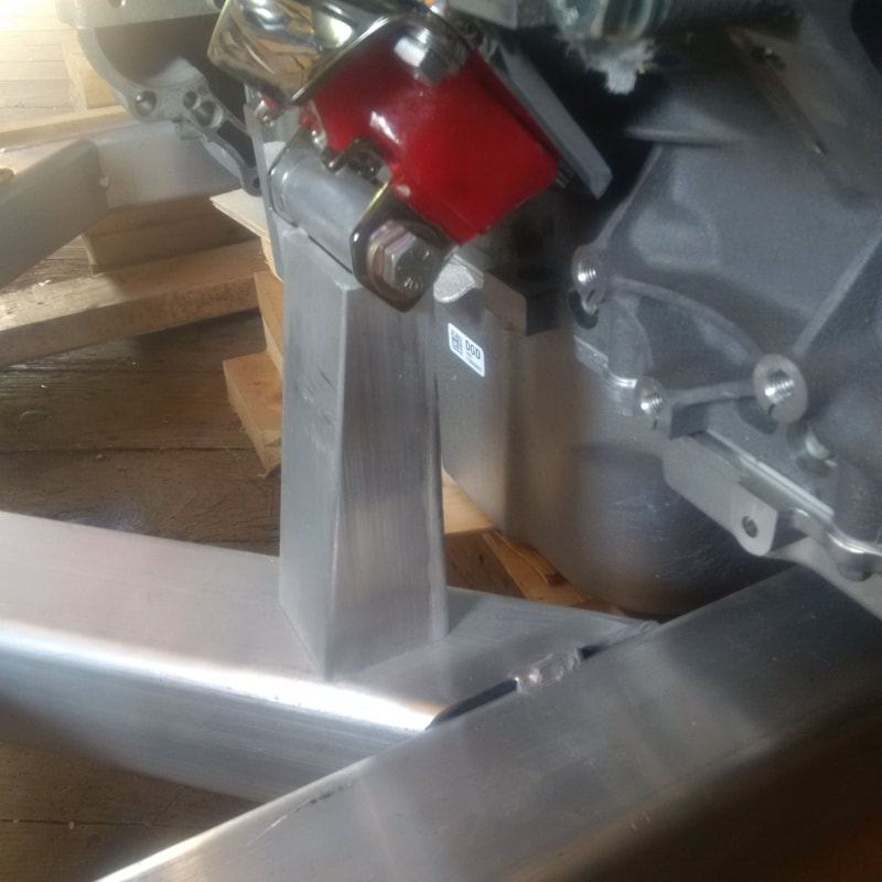
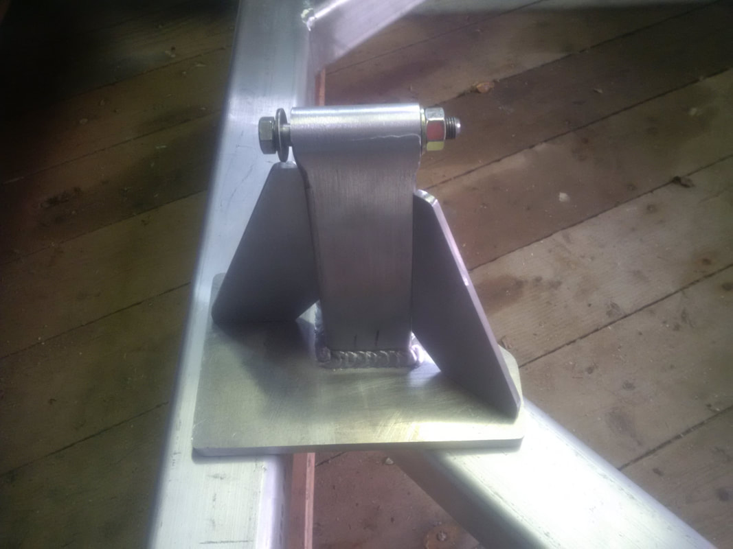
After some sanding, trimming and fitting, the passenger side mount is sitting in place. I still need to add a couple gussets and then move over to the other side of the engine and repeat the same process. Before I weld them to the cradle, I will bore them out to take some stainless steel bushings so that the hardened bolt doesn't wear through the aluminum boss.
After some sanding, trimming and fitting, the passenger side mount is sitting in place. I still need to add a couple gussets and then move over to the other side of the engine and repeat the same process. Before I weld them to the cradle, I will bore them out to take some stainless steel bushings so that the hardened bolt doesn't wear through the aluminum boss.
|
|
Sept 16 2017
I finally got around to boring out the aluminum round stock to take some 316 stainless steel bushings. The aluminum round stock is 2-3/8" long so I bored the entire length but machined the SS bushing only 1 inch long so I could press them in from each end with an interference fit and still have a small gap between them. I machined the bore of the SS bushings to just have a nice sliding fit on the shank of the bolts. The bolts are 7/16" x 3-1/2" Grade 8, fine thread with hardened nuts and washers. I will now get the top aluminum bosses welded to the bases and then they are ready to weld to the engine cradle. I have some aluminum plate that will be made into gussets to help support the engine mounts. They are about 6-1/2" tall and I definitely don't want them flexing when the engine is under load. They will be similar to the gussets shown a couple images back.
I finally got around to boring out the aluminum round stock to take some 316 stainless steel bushings. The aluminum round stock is 2-3/8" long so I bored the entire length but machined the SS bushing only 1 inch long so I could press them in from each end with an interference fit and still have a small gap between them. I machined the bore of the SS bushings to just have a nice sliding fit on the shank of the bolts. The bolts are 7/16" x 3-1/2" Grade 8, fine thread with hardened nuts and washers. I will now get the top aluminum bosses welded to the bases and then they are ready to weld to the engine cradle. I have some aluminum plate that will be made into gussets to help support the engine mounts. They are about 6-1/2" tall and I definitely don't want them flexing when the engine is under load. They will be similar to the gussets shown a couple images back.
|

|
|
|
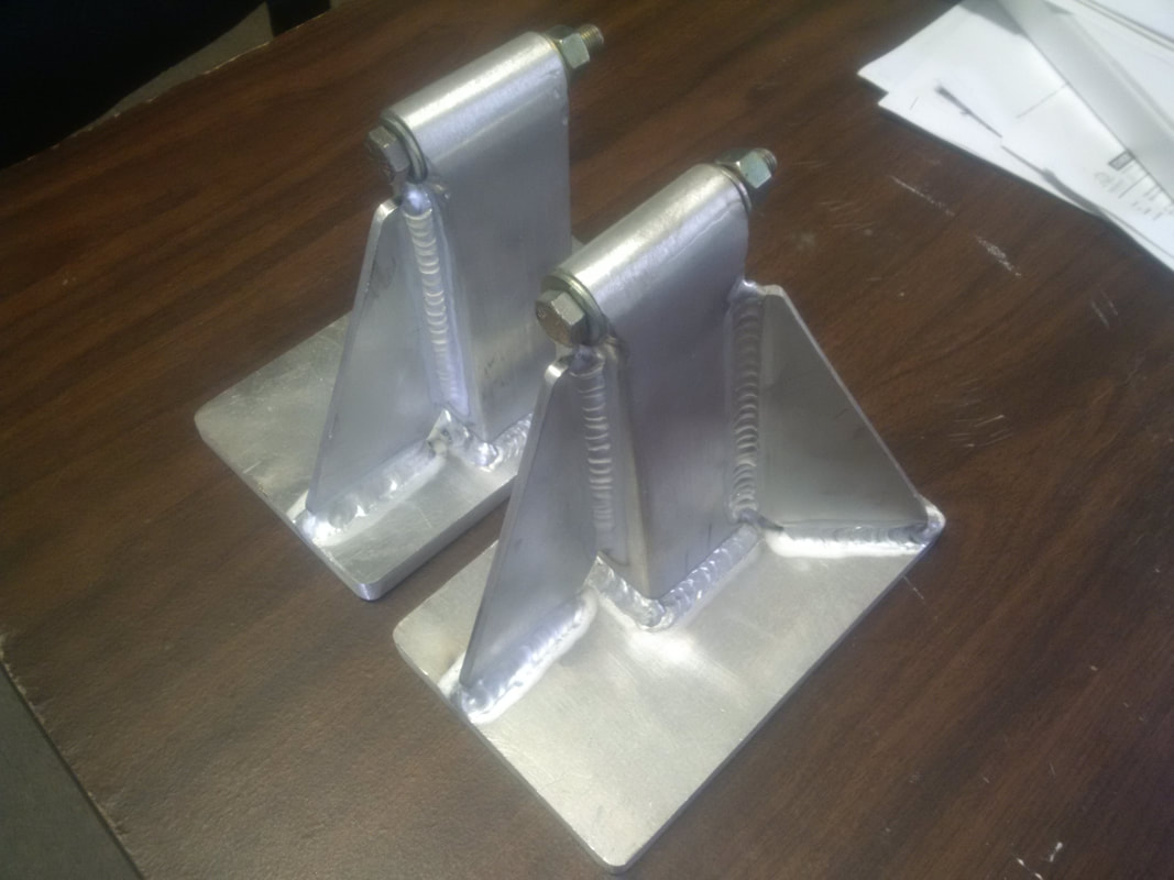
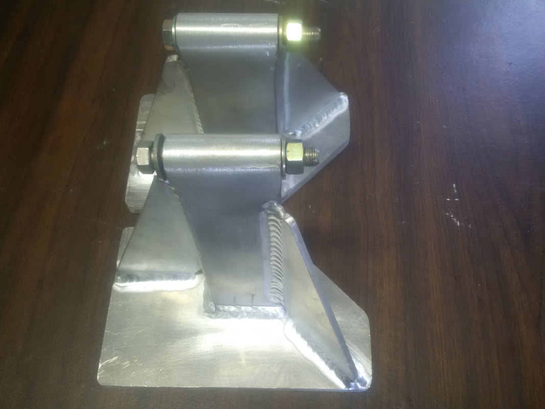
Oct 28 2017
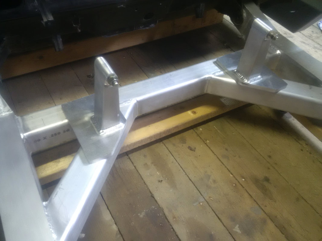
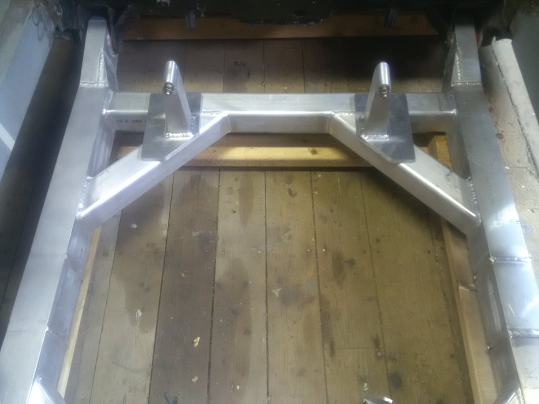
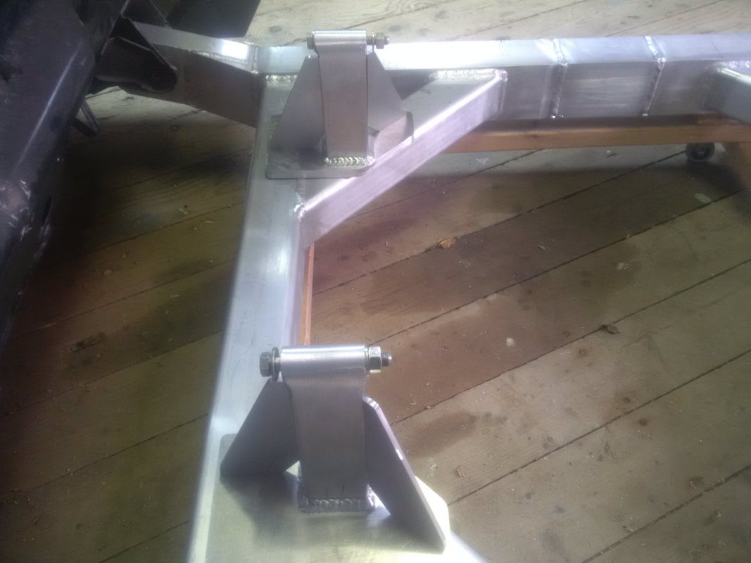
With the mounts all welded, I fabricated a mounting plate for the base of each mount to help spread the load over the cradle structure. Originally, this plate was going to be 1/4" plate but I felt I could lift the engine a little higher so I used 1/2" aluminum plate. Here they are sitting in position on the cradle. Once I have the engine and transmission bolted together and sitting square and level on the cradle in the engine compartment, I'll tack the mounts to the cradle to hold the location of everything.
With the mounts all welded, I fabricated a mounting plate for the base of each mount to help spread the load over the cradle structure. Originally, this plate was going to be 1/4" plate but I felt I could lift the engine a little higher so I used 1/2" aluminum plate. Here they are sitting in position on the cradle. Once I have the engine and transmission bolted together and sitting square and level on the cradle in the engine compartment, I'll tack the mounts to the cradle to hold the location of everything.
|
|

Nov 5 2017
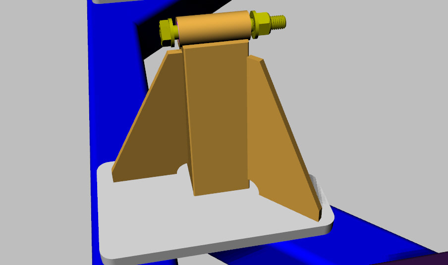
I had mentioned earlier that I had planned to fabricate some small gussets to help stiffen up the engine mounts I had fabricated as they are over 6" tall. While I did taper out the base so that they are wider at the bottom, I just felt that they were a little tall to be unsupported. So I designed two gussets for the front and back of the mount. Here they are in the 3D model as well as the actual fabricated parts. They are cut from 3/16" aluminum plate.
I had mentioned earlier that I had planned to fabricate some small gussets to help stiffen up the engine mounts I had fabricated as they are over 6" tall. While I did taper out the base so that they are wider at the bottom, I just felt that they were a little tall to be unsupported. So I designed two gussets for the front and back of the mount. Here they are in the 3D model as well as the actual fabricated parts. They are cut from 3/16" aluminum plate.
|
|
|
|