The engine cradle
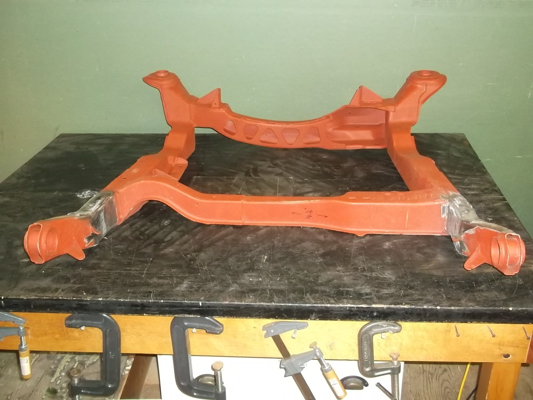
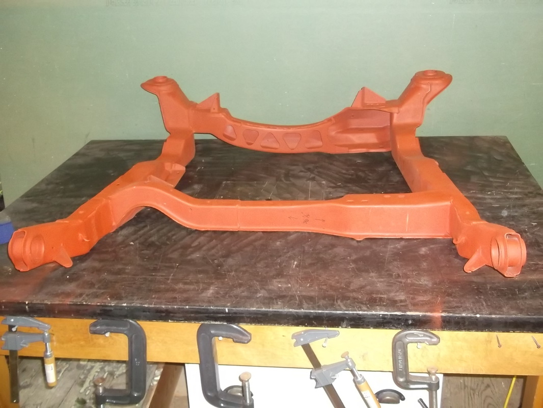
As I had mentioned in the section regarding the chassis stretch, the stock engine cradle was stretched to match the rest of the chassis. However, as I continued the development of the chassis, it soon became apparent that the stock cradle just wasn't going to cut it for this project. First of all, it is not designed to accommodate a V8 engine, either longitudinally or transversely without significant modifications. Secondly, the stock engine cradle is designed around the stock Fiero rear track. Unfortunately, the project car is going to require an 8" track width increase. In my opinion, the best way to accomplish this is to widen the entire cradle. Otherwise I am going to require some very long rear control arms to reach the wider tracker on the rear wheels.
So..... in a nut shell, I have a mint condition 85 Fiero engine cradle with 3" extension for sale. :(
The good news is that it allows me to start from scratch and design a new cradle to exactly meet my requirements both in geometry and strength. The starting point of course is the chassis connections. My new cradle must be able to bolt up to the stock cradle mounts on the lower firewall as well as the align with the new extended lower frame rails. As well, the cradle must have the mounting points for the rear control arms at the correct position in all three axis relative to the chassis. On top of all this, it must be designed to withstand the power of the 400 hp V8 that it will be supporting and yet be light enough to not adversely effect the weight distribution of the chassis.
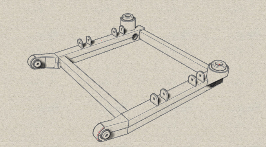
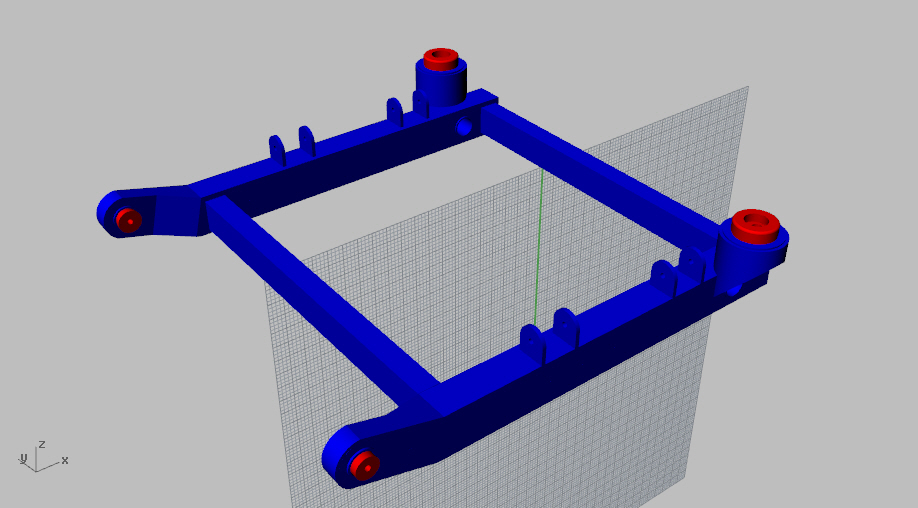
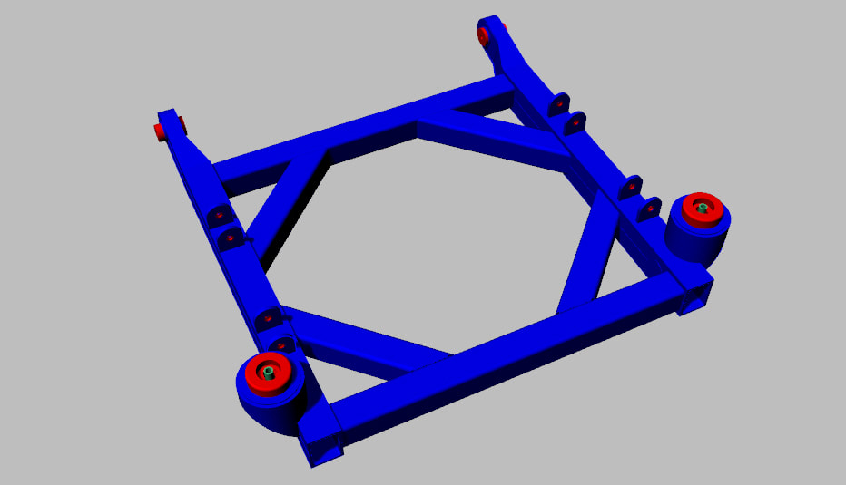
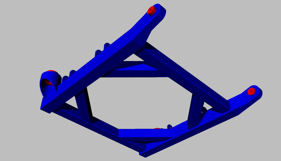
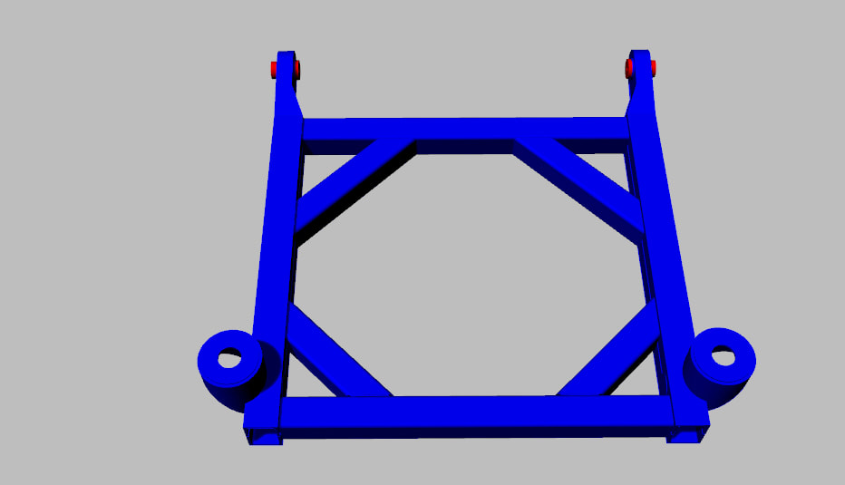
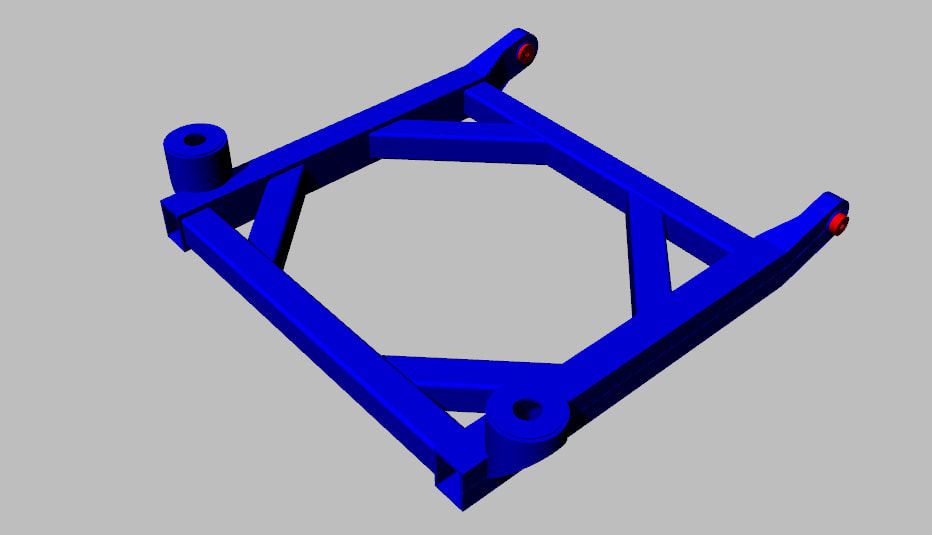
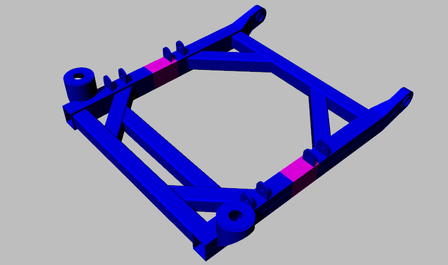
With all this in mind, I decided to design and build an aluminum cradle to meet all the above noted requirements. Here is what I came up with.
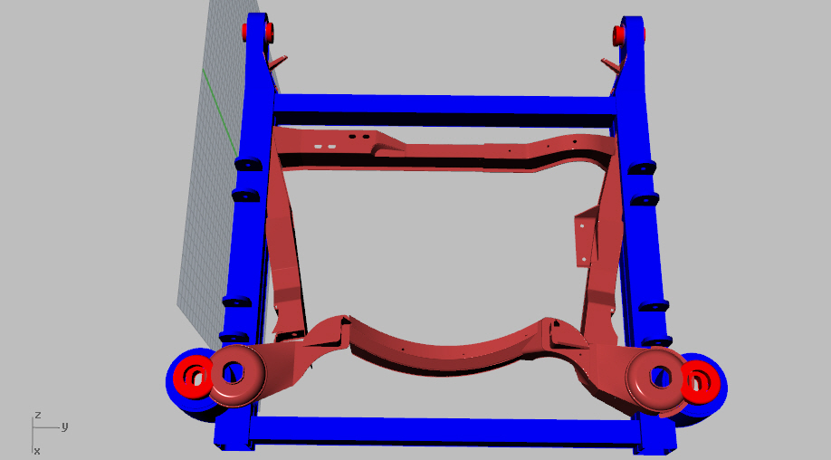
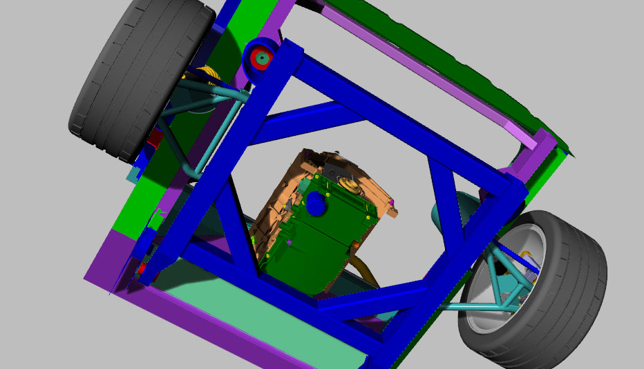
As a reference, here is the new cradle superimposed on the stock Fiero cradle. You can see that I have retained the stock chassis mounting locations front and rear as well as accommodated the wider track of the rear suspension.
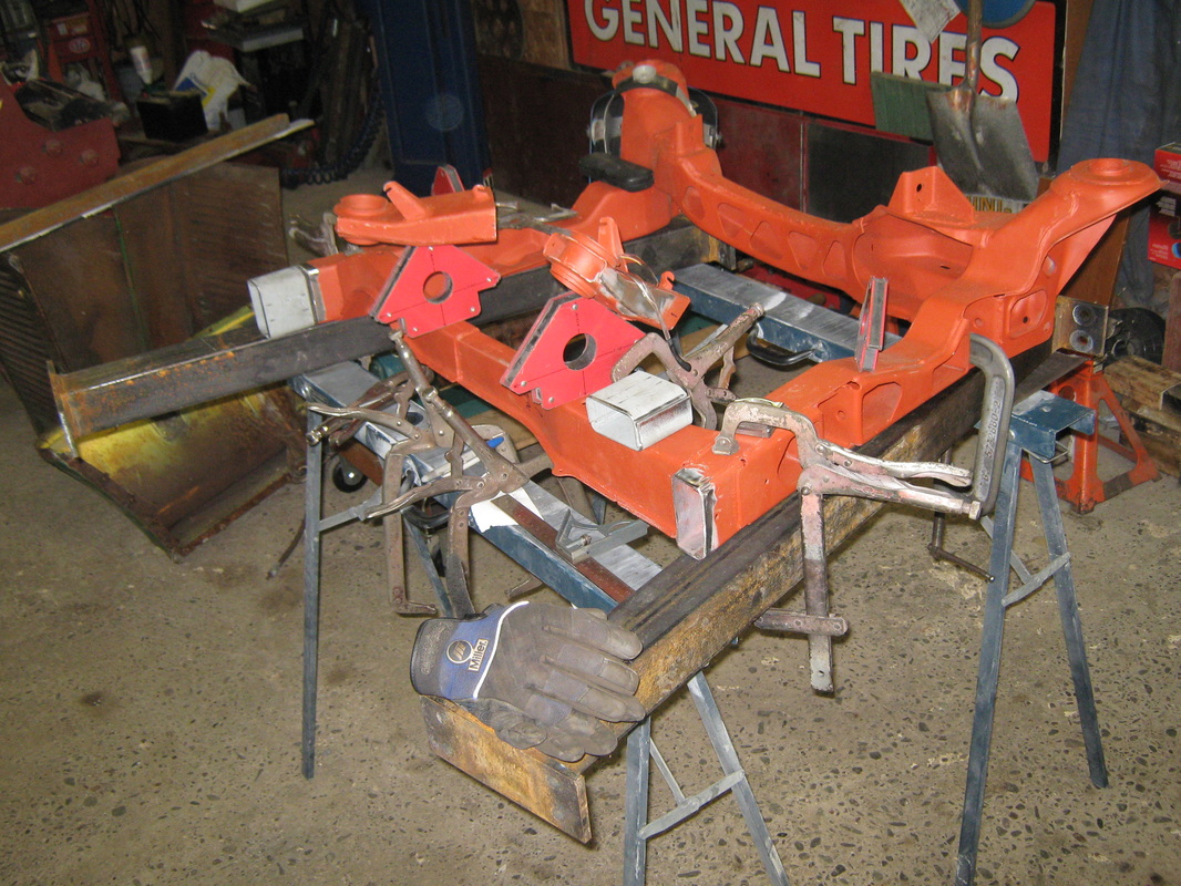
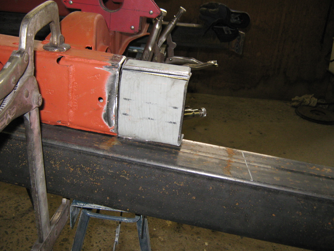
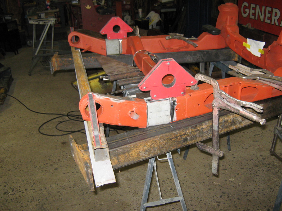
I guess that even though I will not be using the stock cradle that I stretched 3", I should show a few images and photos of the 3" stretch as it might be of interest to someone someday........maybe.
Feb 21 2015
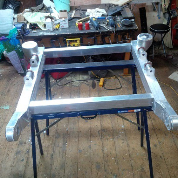
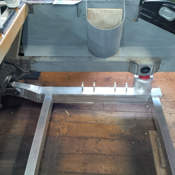
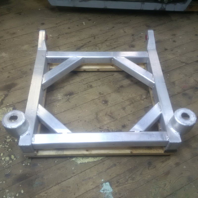
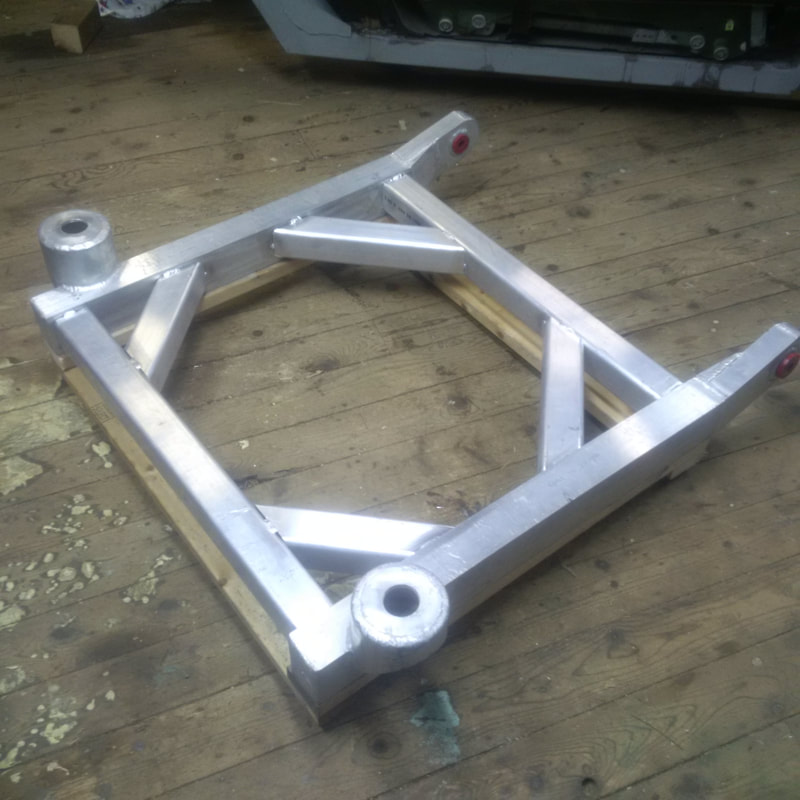
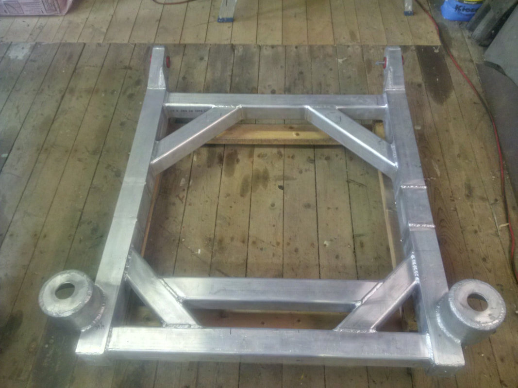
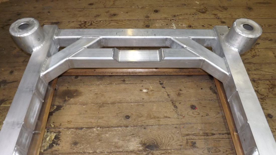
And here is the new aluminum cradle welded and ready to fit in the chassis. I designed it to accept the OEM poly mounting bushings front and rear. At this point, the transverse members are only tacked in position to hold it all together until I finalize the location of such things as engine and transmission mounts etc. As well, the rear control arm lugs are only sitting in position until I have finished the design and construction of the rear control arms.
And here is the new aluminum cradle welded and ready to fit in the chassis. I designed it to accept the OEM poly mounting bushings front and rear. At this point, the transverse members are only tacked in position to hold it all together until I finalize the location of such things as engine and transmission mounts etc. As well, the rear control arm lugs are only sitting in position until I have finished the design and construction of the rear control arms.
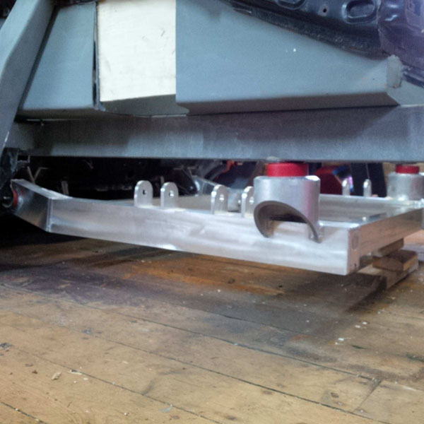
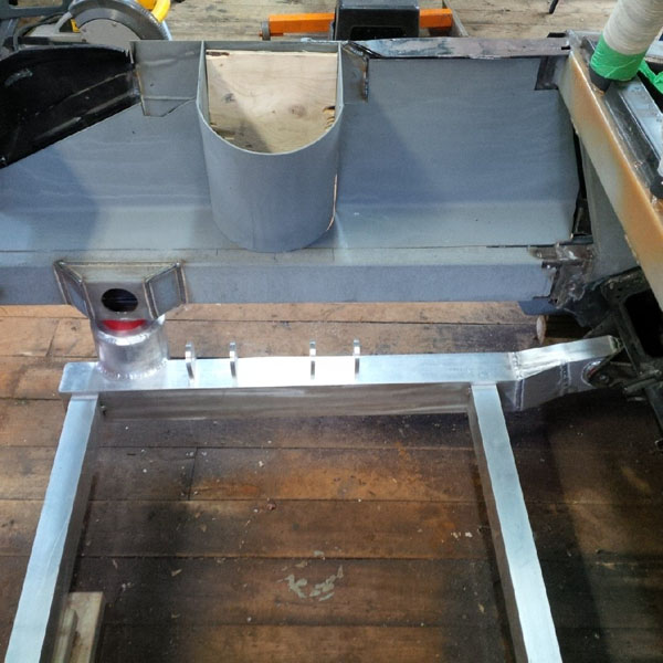
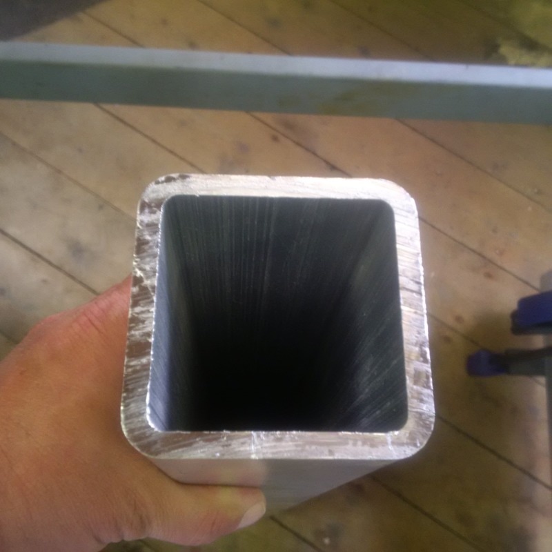
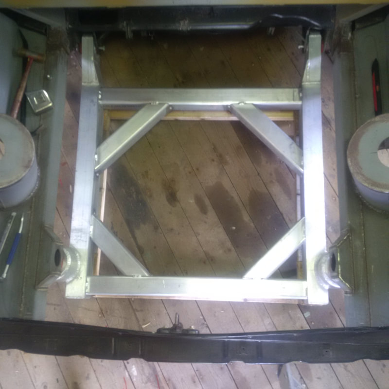
The longitudinal frames of the cradle are 4" x 3" x 1/4" HSS and the transverse frames are 3" x 2" x 1/4" HSS. The aluminum HSS is grade 6061-T6 aluminum. Here is the cradle in position under the chassis with the poly bushings installed.
Nov 12 2015
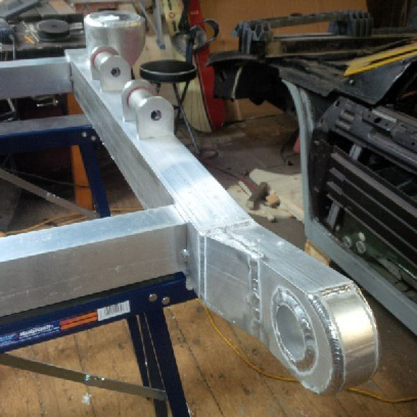
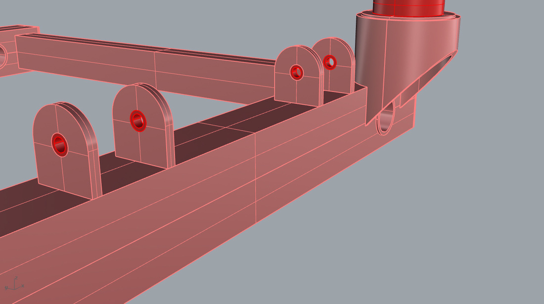
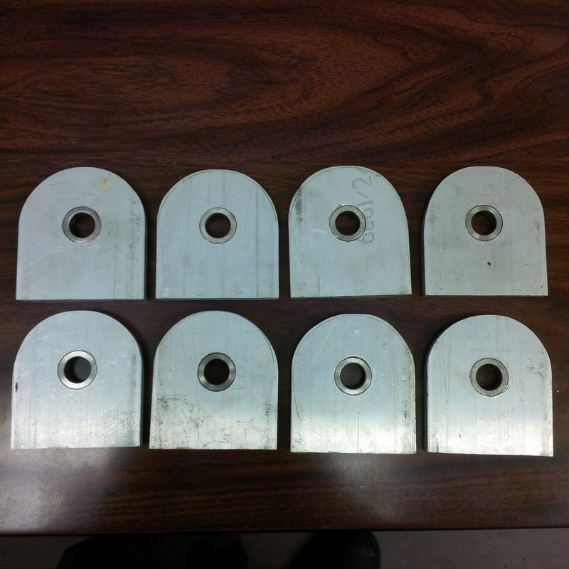
The brackets that connect the control arms to the cradle are aluminum of course so to prevent the hardened control arm bolts from wearing the holes in the brackets, I installed bushings in all eight holes. The bushings are 316 SS and are pressed into the aluminum with a interference fit.
The brackets that connect the control arms to the cradle are aluminum of course so to prevent the hardened control arm bolts from wearing the holes in the brackets, I installed bushings in all eight holes. The bushings are 316 SS and are pressed into the aluminum with a interference fit.
Dec 26 2015
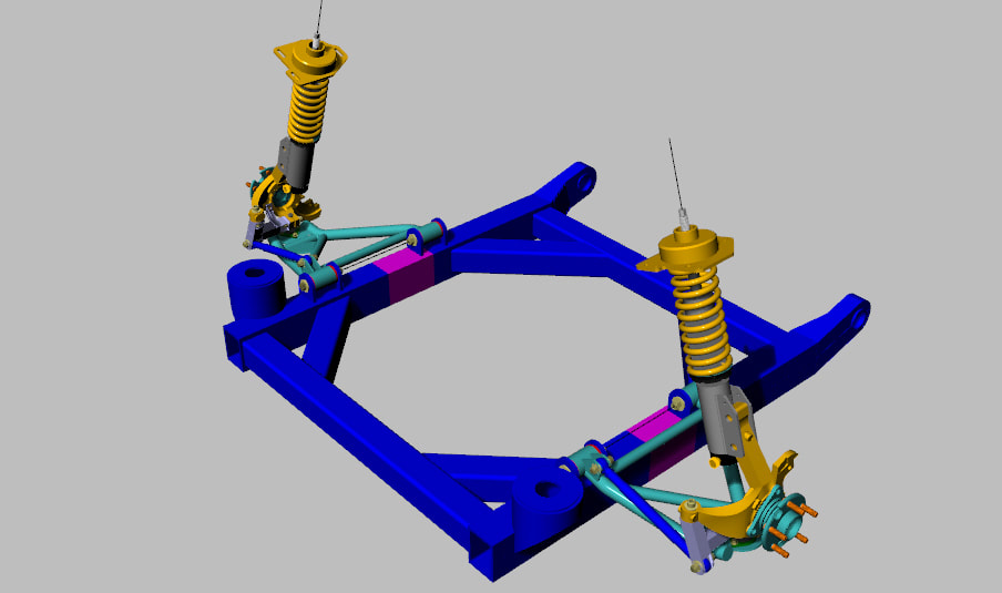
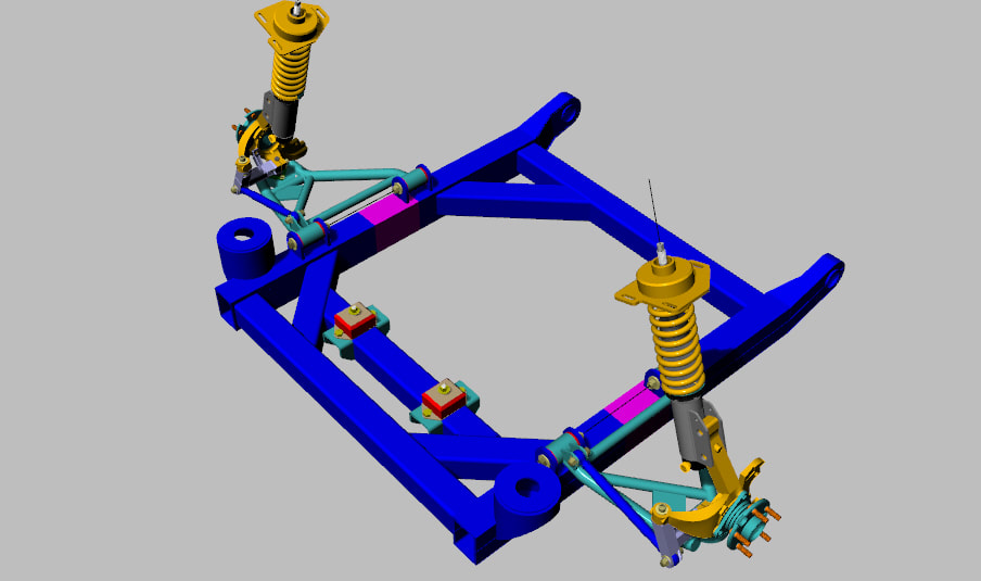
As you may have seen in the rear suspension section, I have finalized the components and located them on the cradle to confirm the various dimensions match my drawings of the assembly. Here is the cradle with rear suspension in place.
As you may have seen in the rear suspension section, I have finalized the components and located them on the cradle to confirm the various dimensions match my drawings of the assembly. Here is the cradle with rear suspension in place.
Just for fun, I laid my stock cradle with a 3" stretch on top of my new aluminum cradle to show the difference between the two. Its clear in this picture how the new cradle design helps achieve the wider rear track needed for the 355 body. The forward end of the cradles are the same width, however, in this picture they appear to be quite different. Its just an optical illusion.
As you can see, Santa did not bring me the LS1 engine and Audi 6 speed gearbox that I had been asking for. Of course, with the current state of the Canadian dollar, you can't really blame Santa for shying away from a $10,000 engine. But there is always next year.
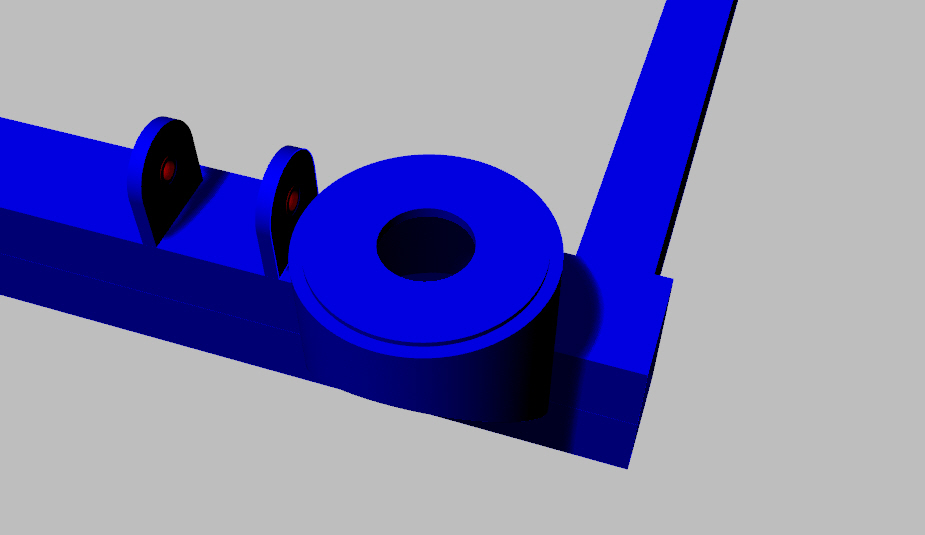
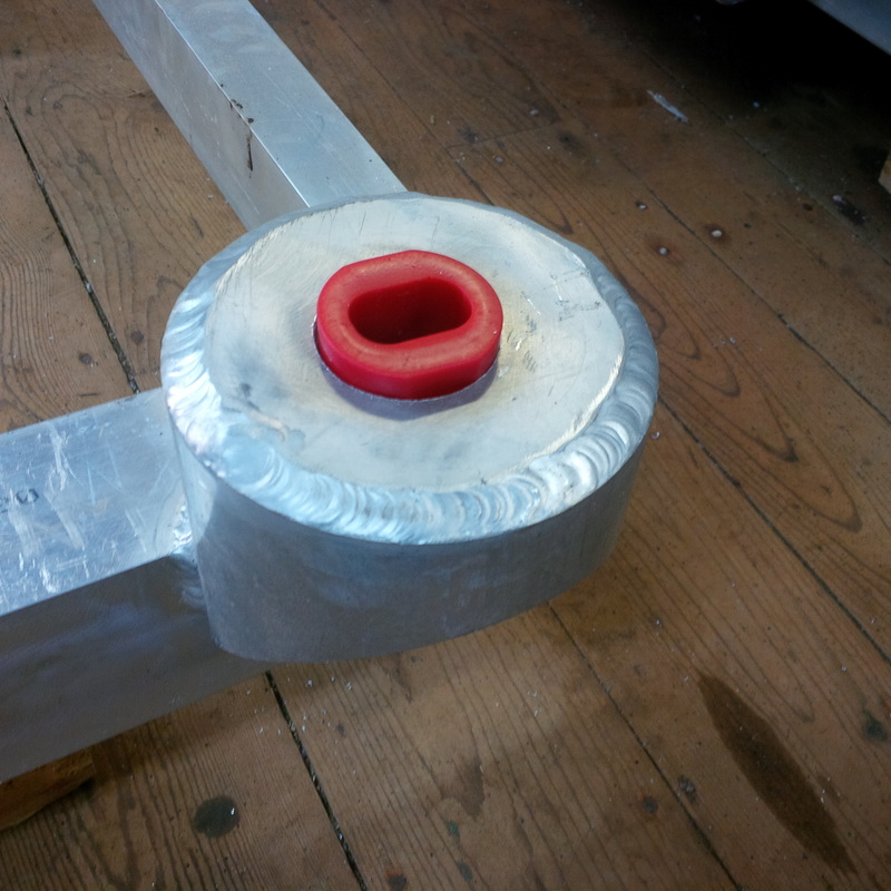
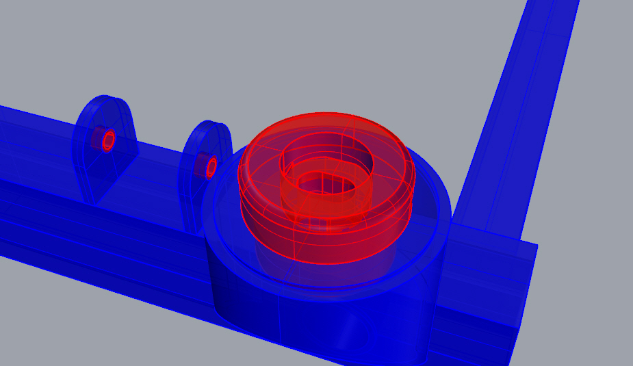
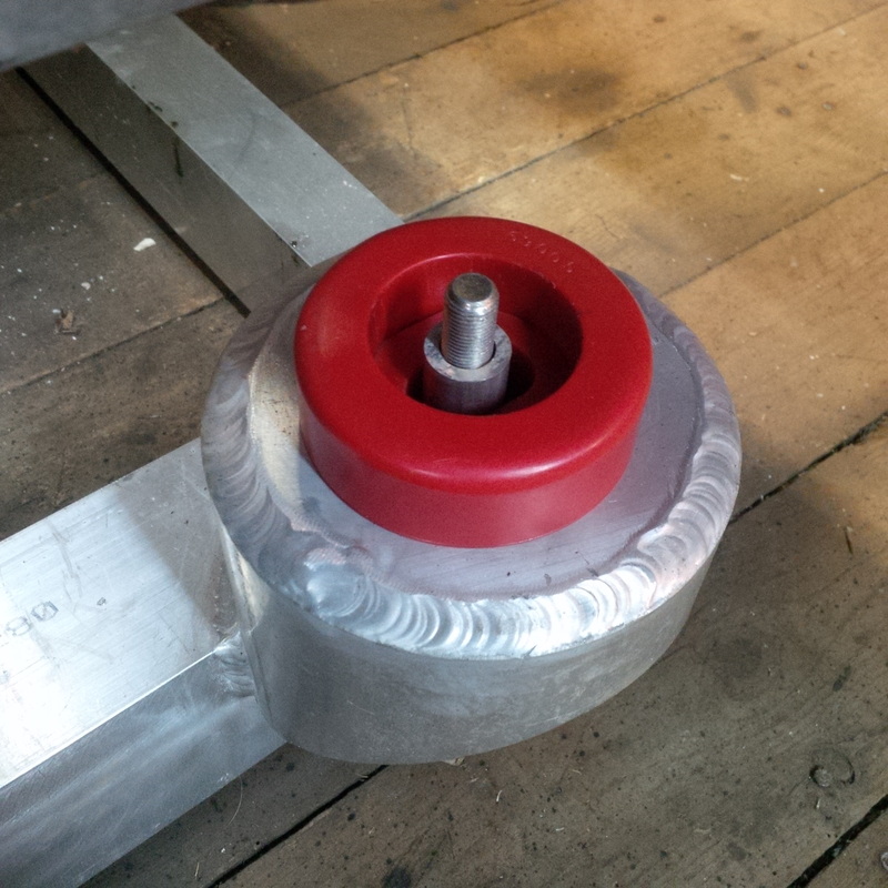
So, after taking a few key measurements of the rear suspension assembly and snapping a few motivational pictures, I striped the suspension down and put all the components back in their respective boxes for safe keeping for now. The next step for the cradle is to mount the rear poly bushings. I am using the Prothane bushings that are suitable for stock cradles. The first step is to drill out the mounting pad to allow the lower half of the 2 piece bushing to protrude up through the mount. Here is a drawing and photo showing the 2" dia hole for the lower half of the bushing.
So, after taking a few key measurements of the rear suspension assembly and snapping a few motivational pictures, I striped the suspension down and put all the components back in their respective boxes for safe keeping for now. The next step for the cradle is to mount the rear poly bushings. I am using the Prothane bushings that are suitable for stock cradles. The first step is to drill out the mounting pad to allow the lower half of the 2 piece bushing to protrude up through the mount. Here is a drawing and photo showing the 2" dia hole for the lower half of the bushing.
With the 2" hole drilled, the lower part of the poly bushing slip right into place from the bottom with lots of the bushing hub protruding upward for the upper part of the bushing to fit down over the hub.
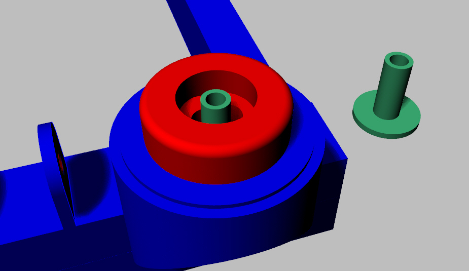
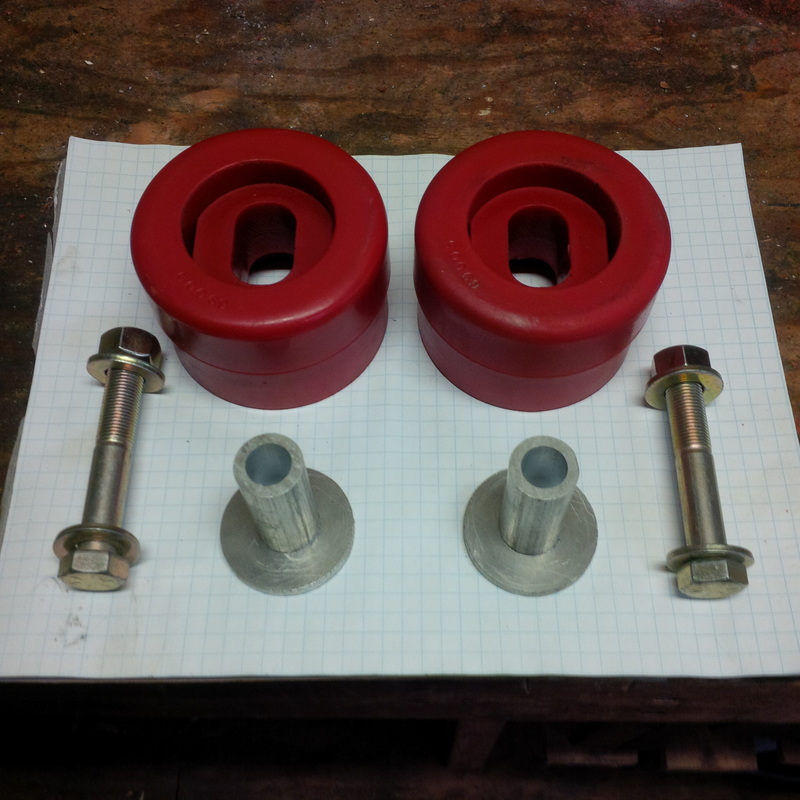
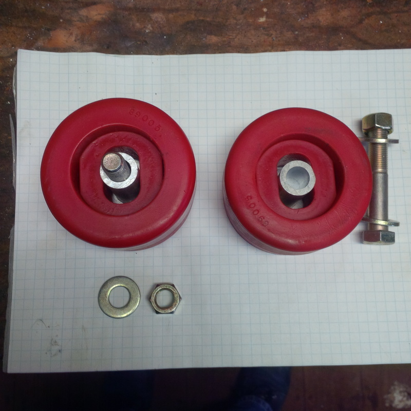
My plan is to use 1/2" dia bolts to secure the rear end of the engine cradle to the lower frame rails. As the hole in the bushing is 3/4" dia., I will fabricate a spacer with an attached washer to locate the bolt on the middle of the poly bushing.
Jan 6 2016
Here are the rear cradle bushings with the aluminum spacer to help hold the 1/2" x 3" NF bolt in the center of the bushing.
Here are the rear cradle bushings with the aluminum spacer to help hold the 1/2" x 3" NF bolt in the center of the bushing.
June 4 2017
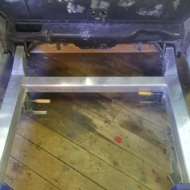
Now that I have my engine sitting in the garage, its time to start working on finalizing the engine cradle design. As I have mentioned, the two main longitudinal cradle rails are completed and I used some 2" x 4" x 1/8" rectangular aluminum tubing to temporarily represent the transverse frame rails. I have begun drawing the LS3 engine by starting with the oil pan as this is the first part that will be close to interacting with the engine cradle structure. The forward transverse cross frame will be constructed out of 3" x 3" x 1/4" HSS ( Hollow Structural Shape). I think I mentioned this before but these aluminum extrusions have filleted corners inside and out which make them suitable as structural sections with stress raising corners avoided.
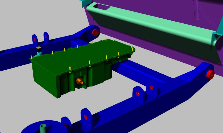
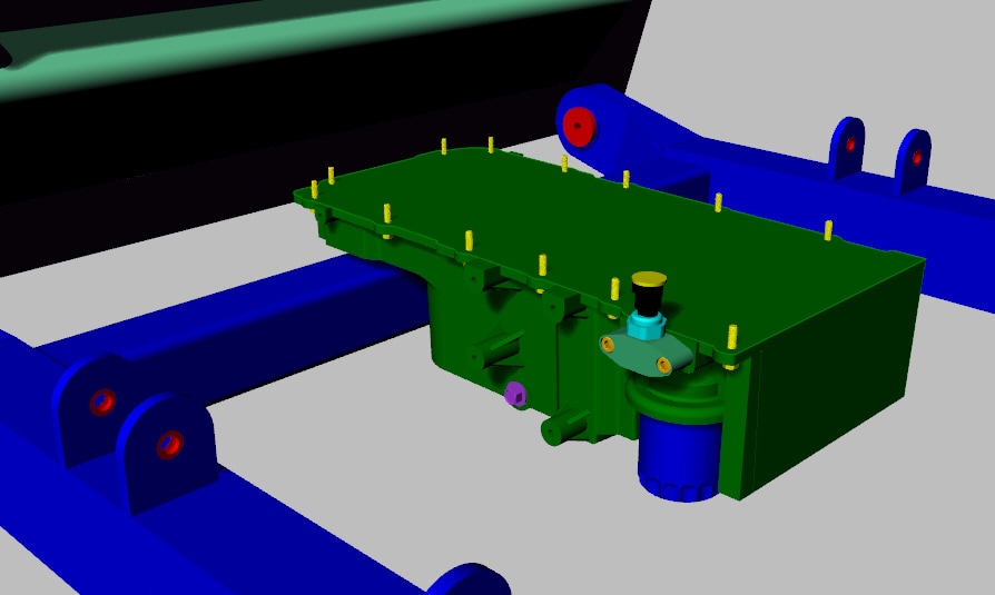
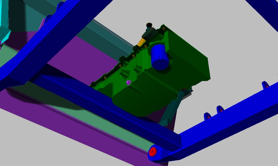
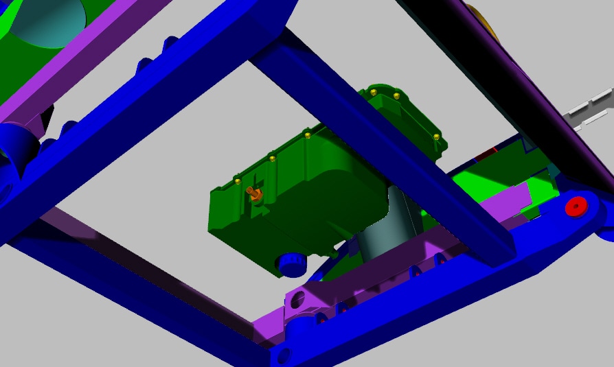
With this front cross member in place, it was time to check for clearance with the LS3 oil pan. When researching possible engines, I did get enough info on the oil pan that came with the crate engine so I had a pretty good idea that it's geometry would suit my engine cradle design and allow the engine to move as far forward as possible. Here are a few images taken from my 3D model with the oil pan located pretty close to how it will be when the engine is installed. I didn't show a side on picture but the bottom of the oil filter is just slightly higher than the underside of the engine cradle.
As I further develop the drawing of the engine and add the engine block, you will see that the forward engine mounts on the block will line up very well with the front engine cradle cross member. Actually, that is only a half truth. The LS3 engine mount locations on the block are actually set quite far back from the front of the engine. However, it just so happens that there are a number of after market engine mount manufacturers who make engine mount relocation kits that move the mounts further forward on the block so that the LS3 crate engine can be used in earlier model muscle cars. Just my luck it seems.
July 29 2017
With the rear lower frame rails completed, except for final welding, its time to work on the aluminum engine cradle. As I have noted above, I have plans to install two transverse cross rails made from 3" x 3" x 1/4" square structural tubing. The fwd one will pass under the front recess of the LS3 oil pan and the rear rail will pass under the 01E gearbox. Both of these transverse rails align nicely with the future engine and transmission mounts I plan to build. Because this engine / gearbox combination is not only much heavier than the stock 4 cyl / 5 speed gearbox, it is also more than 4 times the stock horsepower. This necessitates that the aluminum engine cradle is going to have to be strong. To improve on the basic square design of the cradle shown above, I have decide to add additional structural members that tie the longitudinal and transverse frames together. I will use the same 3" x 3" x 1/4" square tubing to triangulate the structure similar to a truss.
With this arrangement, the engine cradle will be sufficiently stiff to resist the bending loads of the engine / gearbox mass as well as resist the twisting / racking forces that the cradle will experience while driving and cornering. The location of these 4 extra triangulated members also line up with the mounting points of the rear suspension control arms on the longitudinal frames. This will help distribute the forces applied to the engine cradle by the suspension.
While this may seem like structure overkill at first glance, keep in mind that this is all built with aluminum that, while significantly lighter than steel by a factor of 3, is also not nearly as strong. I have tried to select structural shapes with radius corners that maximize the aluminum mechanical properties while designing the structure to distribute the forces the cradle will experience. I also keep in the back of my mind that I don't want this cradle to bend and flex excessively during hard cornering and acceleration / deceleration. I put a lot of thought and effort into the design and construction of the rear suspension but its only as good as the structure its connected to. I want this baby to feel like she's riding on rails when its done and having a structurally sound chassis and engine cradle is certainly an important criteria.
I have all the structural members cut and I'll take them to work this week and have one of our master aluminum welders put it all together. It should look impressive when its all done and I'll post pics when its ready. I also need to get working on the 3d model of the gearbox and finish the LS3 as well. Its looking a little incomplete still.
I have all the structural members cut and I'll take them to work this week and have one of our master aluminum welders put it all together. It should look impressive when its all done and I'll post pics when its ready. I also need to get working on the 3d model of the gearbox and finish the LS3 as well. Its looking a little incomplete still.
August 4 2017
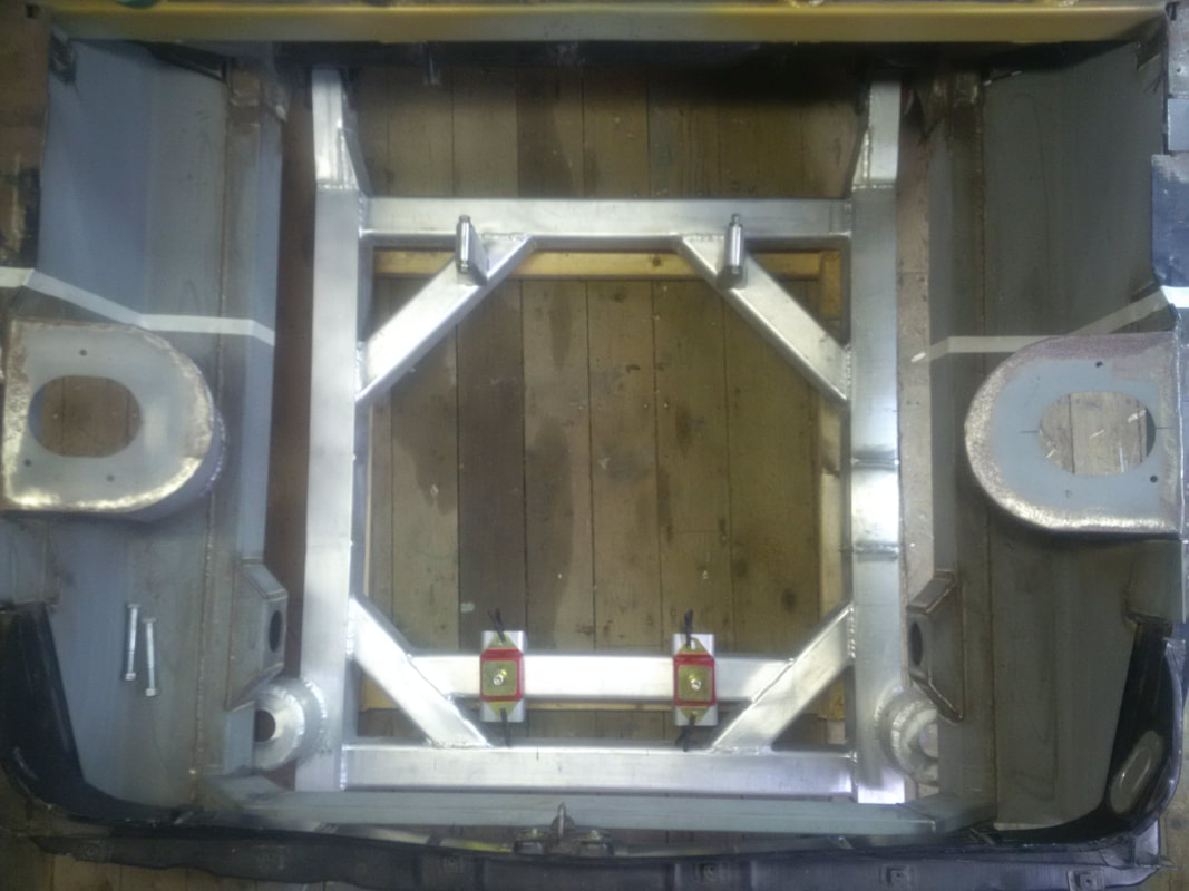
Here is the cradle with all the parts just tacked together. I want to install it back in the chassis to be sure everything bolts back up at the poly bushings before final welding. At this point, the cradle weighs in at 62 lbs. I recall that the stock cradle with the 3" stretch weighed around 50 lbs so my new cradle is definitely heavier even though it is aluminum. However, it is quite a bit larger and structurally more robust so I am happy with it. There will be more parts added for the engine and transmission mounts as well as the attachment points for the rear control arms so its going to continue to grow in weight as time goes on. At this time, I have no plans to lighten the structure with strategically placed holes. I do plan to have the cradle powdercoated when it is completely done but that is off in the future when the engine bay is 100% complete.
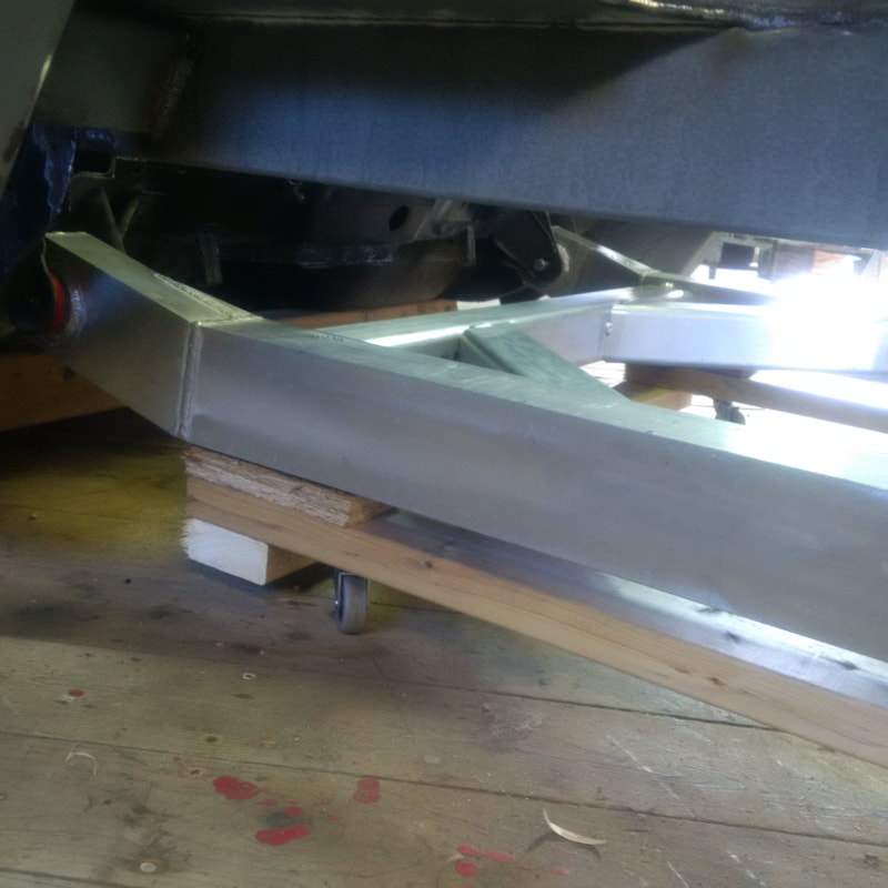
I made a temporary cradle dolly with swivel wheels to roll the structure around. The height of the dolly sets the bottom of the cradle at ride height which is about 5" above the ground.
August 5 2017
Its a special kind of feeling when you roll your engine cradle back in place under the chassis and the mounting bolts go back in with just a little push with the finger tips. :)
Its a special kind of feeling when you roll your engine cradle back in place under the chassis and the mounting bolts go back in with just a little push with the finger tips. :)
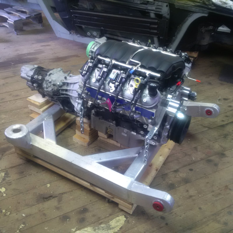
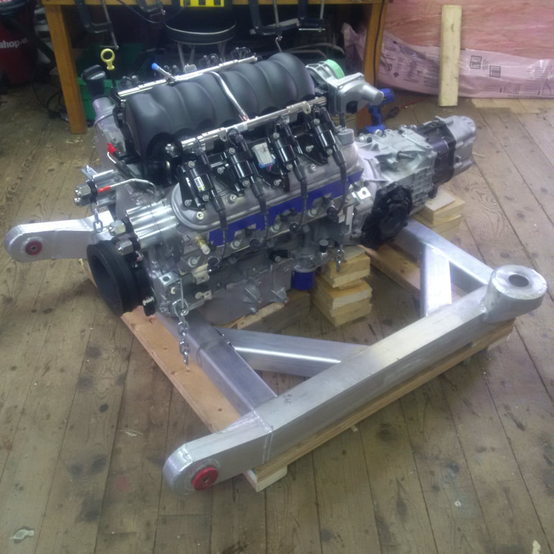
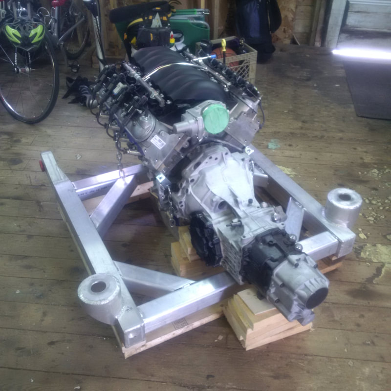
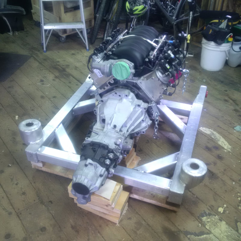
The cradle suddenly does not seem so large with the engine and transmission sitting on it.
Oct 22 2017
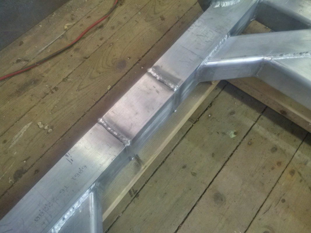
By now, you are probably aware that I have made the decision to stretch my chassis a further 6" to accommodate my longitudinal driveline. Since the point of this exercise is to move the rear suspension further rearward, then I will also have to stretch my aluminum engine cradle to match as that is where the suspension is mounted. This will be a relatively simple matter of cutting the cradle across the two longitudinal frames, just between the angled tube gussets. Then the gap in the longitudinal rails is filled with a matching section of square aluminum extrusion. The material is 1/4" thick so I had the butt joints beveled to achieve a full penetration weld, allowing me to sand the welded seam smooth.
By now, you are probably aware that I have made the decision to stretch my chassis a further 6" to accommodate my longitudinal driveline. Since the point of this exercise is to move the rear suspension further rearward, then I will also have to stretch my aluminum engine cradle to match as that is where the suspension is mounted. This will be a relatively simple matter of cutting the cradle across the two longitudinal frames, just between the angled tube gussets. Then the gap in the longitudinal rails is filled with a matching section of square aluminum extrusion. The material is 1/4" thick so I had the butt joints beveled to achieve a full penetration weld, allowing me to sand the welded seam smooth.
As the rear transverse frame is now 6 inches further back, I have to add an additional transverse frame that will line up with the transmission mounts that I have designed. In case you are wondering, yes, this aluminum cradle is starting to get heavy. :(
Here are a few pics of the cradle with the 6" extension completed with the additional transverse frame added. I have started to sand the extension welds smooth for appearance.
Dec 9 2017
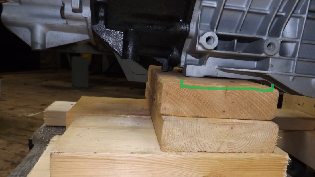
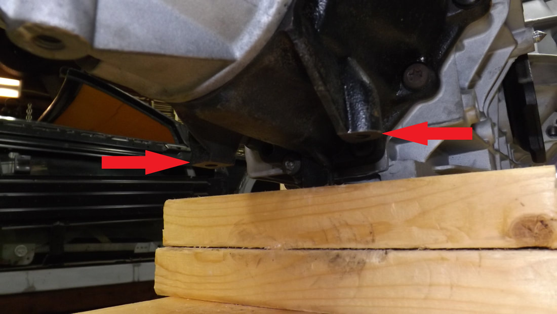
With the engine and transmission bolted together with the adapter plate and then the whole assembly sitting on the stretched cradle, it was apparent that I had a little interference between the underside of the transmission and both rear transverse frames of the cradle. I always knew this was a possibility as I was keeping the engine and transmission as low as possible on the cradle. The area of interference is marked with green. The first transverse frame needed about 1 inch more clearance so I notched out about 6" of the frame in way of the transmission ( offset 1" to the driver side) and bent a piece of 3" x 1/4" aluminum plate to cap the void. I'll get this welded the next time I take the cradle to the aluminum shop.
The rear most transverse frame also had some interference with the transmission but upon closer inspection, I realized that the underside of the transmission actually has two cast legs with threaded holes. I assume these are used for transmission mounts for whatever 2WD Audi this unit was originally installed in. You can see these with the red arrow indicator. So rather than notch the aluminum cradle further, I think I will just cut these two cast legs off with a zip wheel as they have no use in my build.
