struts
July 5 2014
One of the most significant improvements I plan to make to the rear suspension is to replace the stock Fiero rear McPherson struts with high performance coil over struts. And like most improvement to the Fiero, it's not always a simple bolt on replacement. The first thing to remember is that I plan on changing the Fiero suspension geometry by lowering the chassis, widening the chassis and moving the suspension rearward with the chassis stretch. As well as change the geometry of the suspension, I also plan to stiffen the suspension to compensate for the extra weight of the V8 as well as have a reduced range of travel to suit the lowered stance of the car.
With all this to consider, I began my search for a suitable strut. The most difficult aspect is the shortened length required. I found a suitable coil over strut at QA1. They have an extensive selection as well as the technical information I needed to help make the decision.
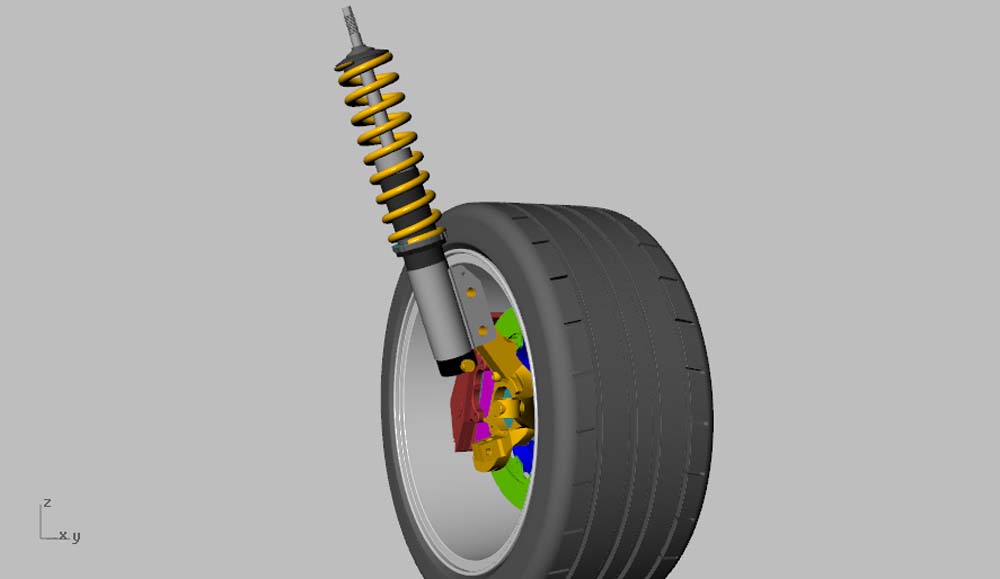
I chose the QA1 Pro Coil Strut System (PN HS606S-12325) which is a single adjustable valve strut with a 325 lb spring. The ride height is adjustable and has a compressed height of 12.10" and an extended height 18.27". I also purchased the adjustable camber plate for the top end to allow easy adjustment of the rear camber. These are QA1 PN CPK106.
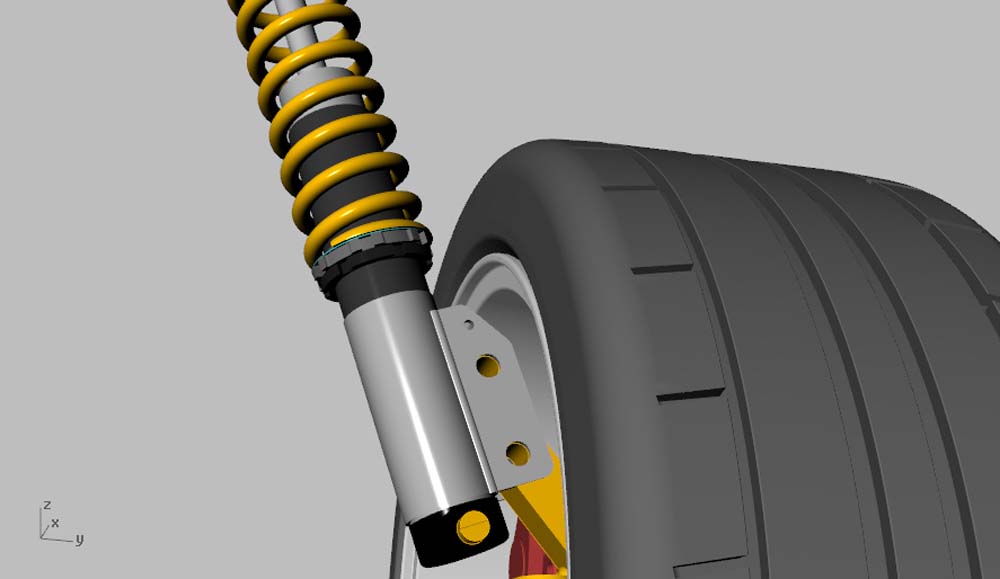
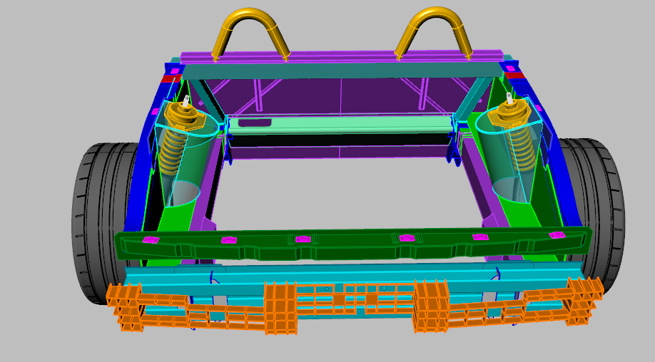
Here is the selected coli over added to my 3D model to check for fit and clearance.
One of the most significant improvements I plan to make to the rear suspension is to replace the stock Fiero rear McPherson struts with high performance coil over struts. And like most improvement to the Fiero, it's not always a simple bolt on replacement. The first thing to remember is that I plan on changing the Fiero suspension geometry by lowering the chassis, widening the chassis and moving the suspension rearward with the chassis stretch. As well as change the geometry of the suspension, I also plan to stiffen the suspension to compensate for the extra weight of the V8 as well as have a reduced range of travel to suit the lowered stance of the car.
With all this to consider, I began my search for a suitable strut. The most difficult aspect is the shortened length required. I found a suitable coil over strut at QA1. They have an extensive selection as well as the technical information I needed to help make the decision.
I chose the QA1 Pro Coil Strut System (PN HS606S-12325) which is a single adjustable valve strut with a 325 lb spring. The ride height is adjustable and has a compressed height of 12.10" and an extended height 18.27". I also purchased the adjustable camber plate for the top end to allow easy adjustment of the rear camber. These are QA1 PN CPK106.
Here is the selected coli over added to my 3D model to check for fit and clearance.
|
|
Sept 14 2014
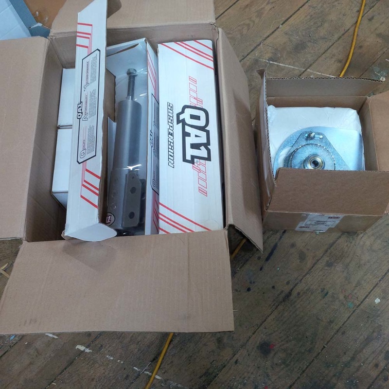
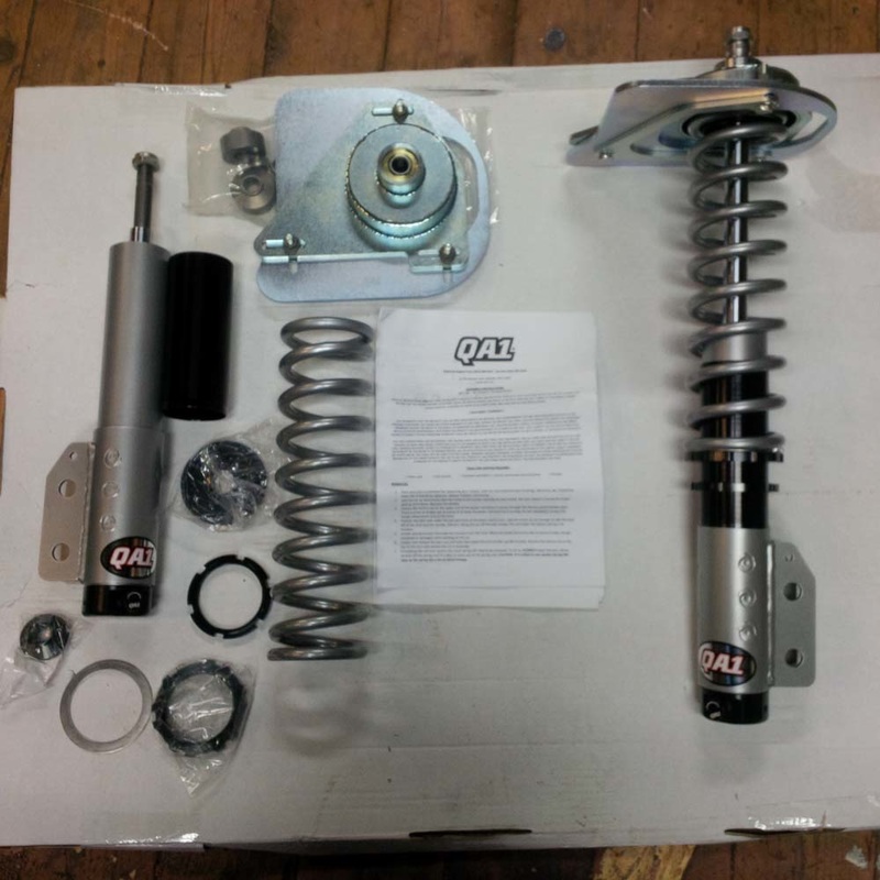
These are the struts delivered from QA1. There are two complete struts with coil over kits as well as two camber plates.
These are the struts delivered from QA1. There are two complete struts with coil over kits as well as two camber plates.
Sept 27 2014
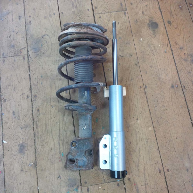
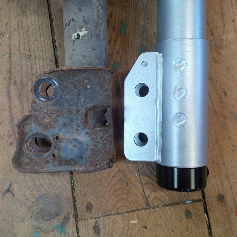
For comparison, here is a new coil over strut along side a stock McPherson strut. The difference is quite obvious, especially with regard to the overall diameter. As well, the stock strut has an oval hole at the spindle mounting point to allow for camber adjustment where as the new strut camber is adjusted at the top camber plate.
For comparison, here is a new coil over strut along side a stock McPherson strut. The difference is quite obvious, especially with regard to the overall diameter. As well, the stock strut has an oval hole at the spindle mounting point to allow for camber adjustment where as the new strut camber is adjusted at the top camber plate.
|
|
|
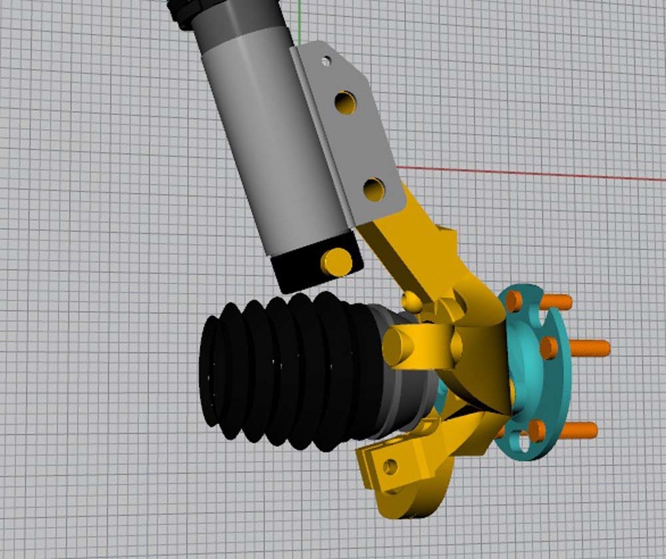
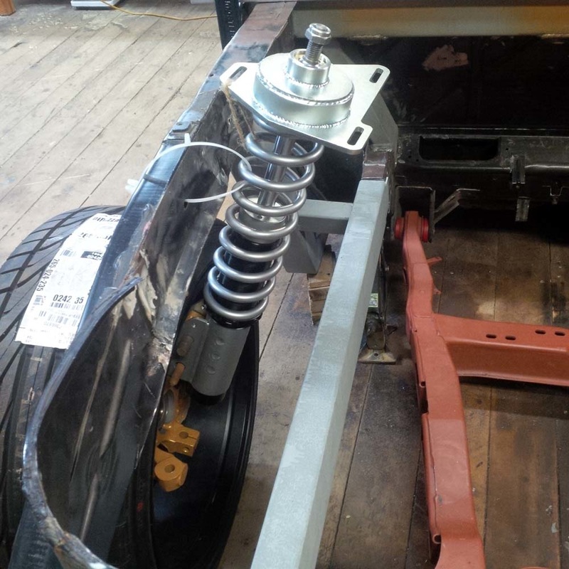
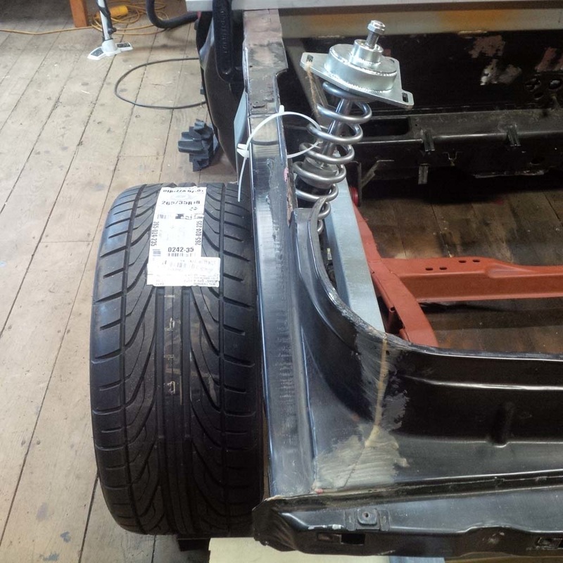
From the photos above comparing the new and old strut, you'll notice that the strut valving adjustment is situated on the lower end of the strut, making it slightly longer than the stock strut. Here are a couple images showing just how close the lower end of the strut is with the drive shaft CV boot.

|
|
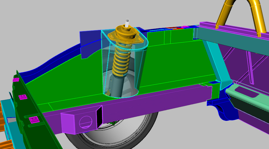
Here are the new struts added to the 3D drawing which shows position and angle of the struts in the strut towers which are ghosted out for clarity. You'll also notice that the notch I added in the upper frame rail provides extra clearance for the strut.
|
|

Sept 28 2014
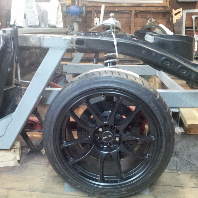
With the struts assembled, It was time to temporarily secure them in place on the chassis and see how they fit. As expected, they fit just like the 3D model said they would.
With the struts assembled, It was time to temporarily secure them in place on the chassis and see how they fit. As expected, they fit just like the 3D model said they would.
|
|
April 26 2015
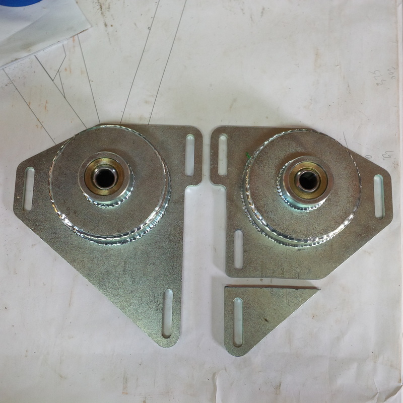
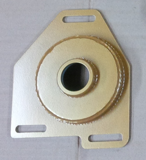
The camber plates I purchased are actually camber / caster plates designed for the front suspension of a GM vehicle. I have to modify them slightly by shortening them up to fit the size of my smaller custom strut towers. Here is a picture showing one modified and the other still stock. You can see that not only did I shorten it, but I added a third slotted hole to replace the one lost by trimming the part.
The camber plates I purchased are actually camber / caster plates designed for the front suspension of a GM vehicle. I have to modify them slightly by shortening them up to fit the size of my smaller custom strut towers. Here is a picture showing one modified and the other still stock. You can see that not only did I shorten it, but I added a third slotted hole to replace the one lost by trimming the part.
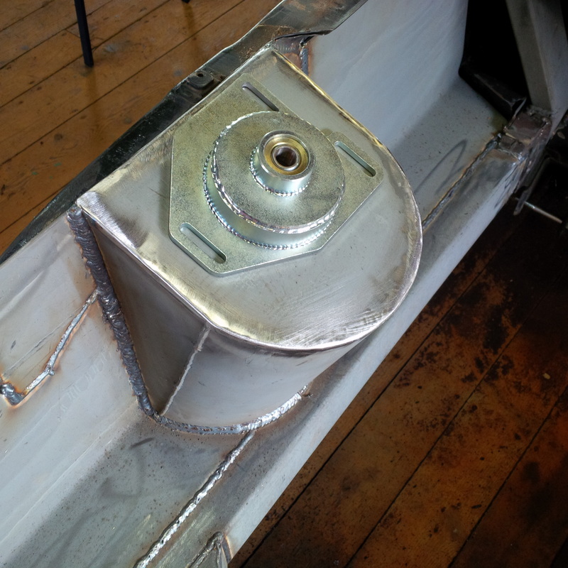
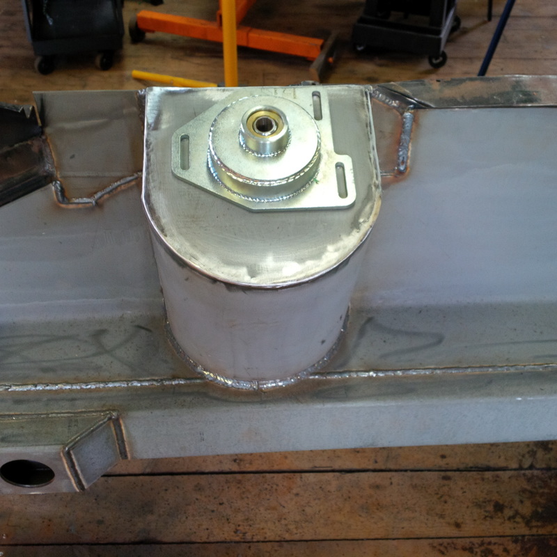
Here is how the trimmed camber plate looks on the strut tower. I'll remove the spherical bearings and send them for powder coating.
|
|
May 4 2015
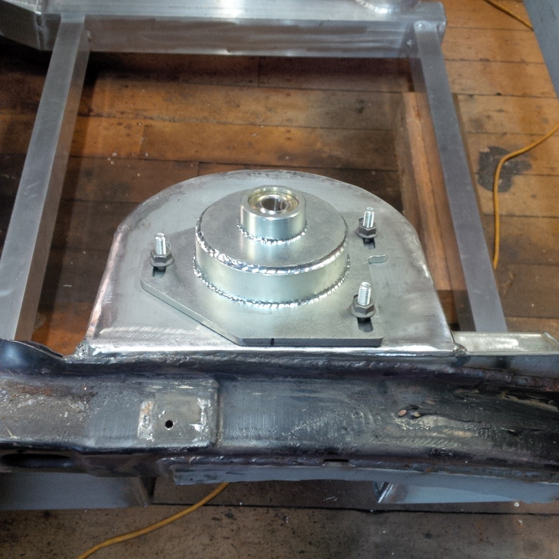
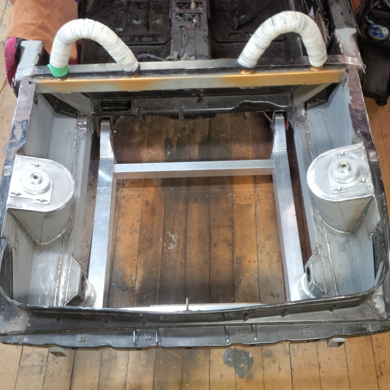
I drilled the top of the strut towers to take the three 8 mm camber plate bolts. I fitted temporary bolts and nuts for now. In the position shown, that will give my rear suspension about 0.5 degrees negative camber. There is just over 1 degree of negative camber available. If I feel that I want more than that at a later date I can either extend the slotted holes or drill the top of the strut tower with new bolt locations.
I drilled the top of the strut towers to take the three 8 mm camber plate bolts. I fitted temporary bolts and nuts for now. In the position shown, that will give my rear suspension about 0.5 degrees negative camber. There is just over 1 degree of negative camber available. If I feel that I want more than that at a later date I can either extend the slotted holes or drill the top of the strut tower with new bolt locations.

|
|
Dec 19 2015
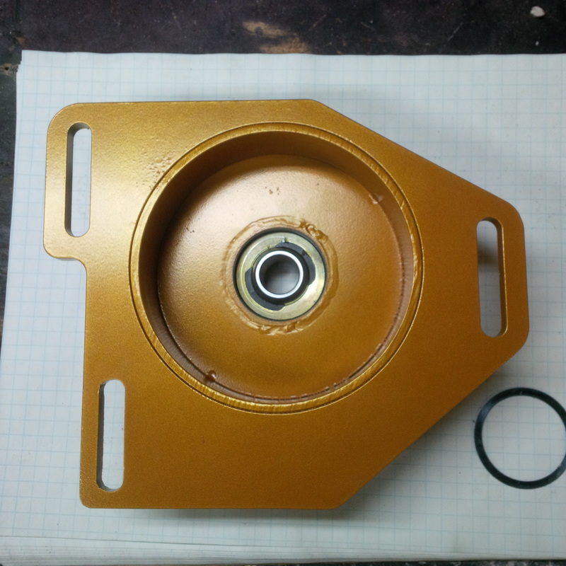
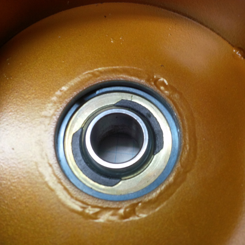
The strut camber plates are back from being powdercoated and are ready to have the spherical bearings installed. I pressed them in with my bearing press and then installed the spring washer to lock them in.
The strut camber plates are back from being powdercoated and are ready to have the spherical bearings installed. I pressed them in with my bearing press and then installed the spring washer to lock them in.
|
|
