Suspension analysis
Feb 20 2016
The following section involves the analysis of my new front suspension geometry. While I did start my new design with a clean sheet of paper, there are a number of criteria that I wanted to incorporate into my design to make it:
a.) fit the existing Fiero front frame rails and mount to the stock locations on the frame rails
b.) keep the structure of the new cross member as simple as possible for ease of fabrication
c.) accommodate the required wider track width of the 355 body style
d.) accommodate the lower stance required to suit the 355 body style
e.) utilize the front wheel and tires I have purchased for the car
f.) utilize after market wheel bearings, ball joints, control arm bushings etc
g.) and of course try to maintain or improve on the stock suspension performance
With all these design criteria taken into account, the actual design of the front suspension was a fairly straight forward process and being able to model the design in 3D as I went along made it even easier to make slight modifications where necessary.
After many repeated and thorough reviews of my friend Dave's front suspension design and analysis, I settled on a few basic geometry settings.
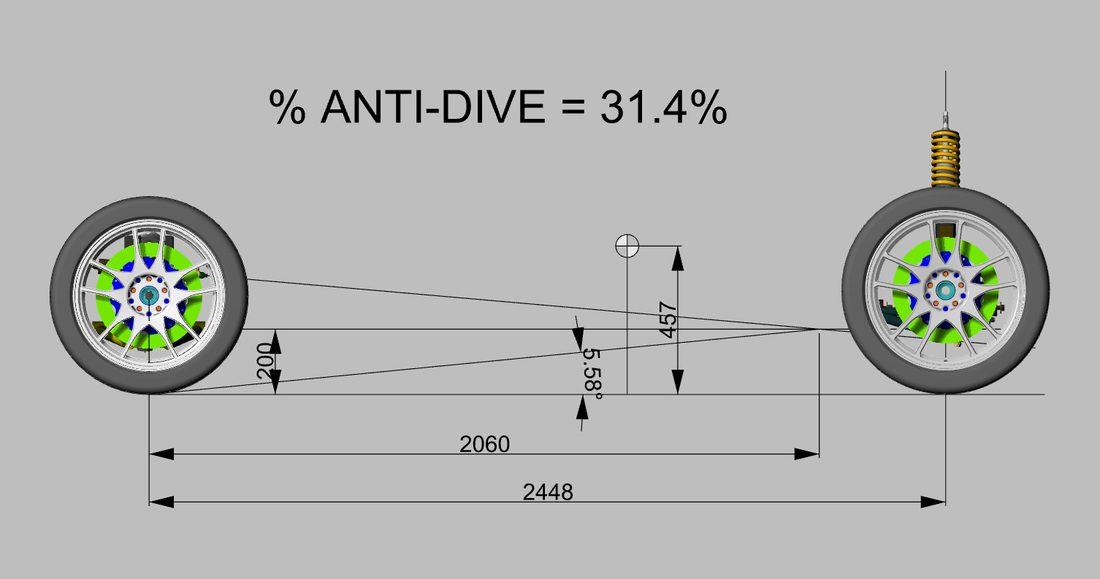
1. set the upper control arm at an angle of 5 degrees to accommodate suitable anti-dive characteristics
2. set the kingpin angle at 5.67 degrees to get a suitable scrub radius
3. set the caster to 5 degrees
4. set the camber to 0 degrees
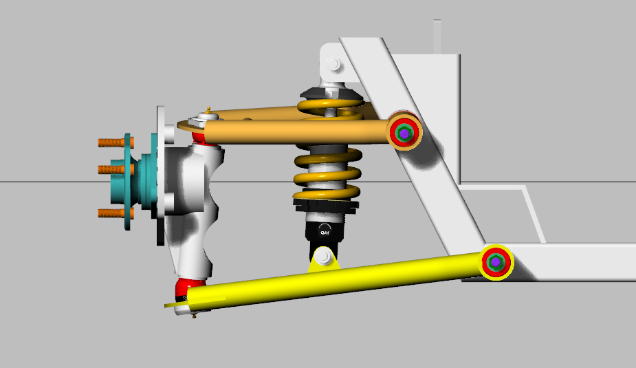
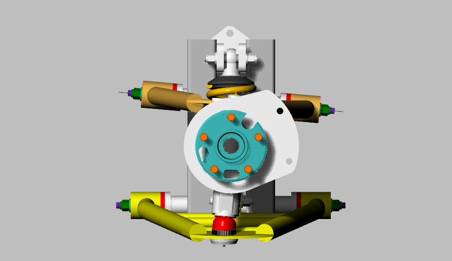
Here are a few images that show the graphical analysis of the suspension travel through 2" of jounce and 2" of rebound. I may add another inch of travel to my analysis even though I won't have that much room for the wheel travel inside the front fender. I will post the numerical data later once I have it compiled in tabular format.
Feb 22 2016
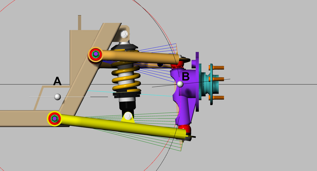
While tabulating the results of the analysis, it quickly became evident that I had a significant issue regarding my geometry. As you may be able to see in the side view of the suspension, as my suspension goes through jounce, the angle of the upper control arm causes the top end of the spindle to kick outwards. As my static position is with zero degrees of camber, any motion outward generates a positive camber value. I definitely don't want this.
I won't post the tabular results of this problem. However, it is a simple fix to move the upper control arm to correct the issue. Once I have the correction made and carry out the analysis again to get the results I desire, I will post the new design and data with supporting graphs.
Feb 24 2016
Comments:
Dave
2/24/2016 21:39:45 The front suspension drawings are looking really good there Graham. Are you using anything other than the CAD program to calculate your geometry changes as you cycle the suspension through its range of travel?
Reply
Graham
2/24/2016 22:33:05
Hi Dave
I am just using my 3D model of the suspension and converting the linkages and pivots to a wire frame diagram. As I cycle the lower control arm through X degrees of jounce and rebound, I make the upper control arm move about its own axis of rotation, using the linkage of the spindle do dictate its motion. From the fixed 3d axis of the drawing I can measure angles, distances and displacement of the various linkages and points of rotation like the upper and lower ball joints. Its a little tedious but its very accurate. My first mistake was moving my linkages in imperial units rather than increments of 10mm like your data is recorded.
Feb 28 2016
Well despite a busy work week, I managed to finish off the revised suspension design to help correct for the poor geometry kinematics I was experiencing. For those of you following along and know about suspensions, it was probably clear to you that the static angle of my upper control arm was too steep and it was pushing the top of my spindle outward during jounce. And since my static camber is 0 degrees, any movement outward was causing positive camber. Not good. :(
So I reduced the angle of the upper control arm and made other changes such as slightly alter the control arm length, upper ball joint angle as well as a few other small items which were necessary to keep everything aligned and fitting together properly.
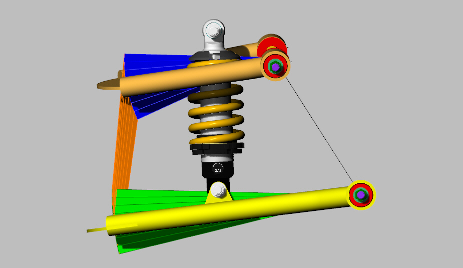
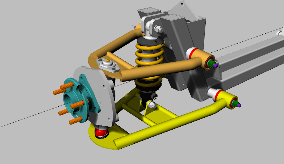
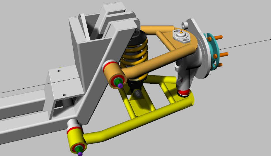
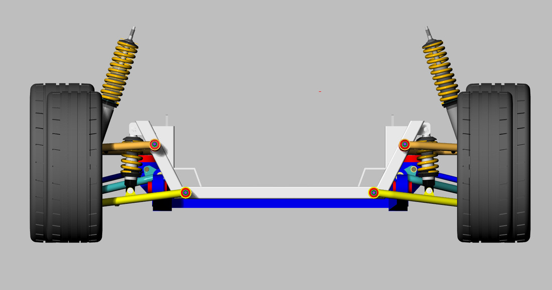
Here are a few images showing the new front suspension geometry. I'll be honest and tell you I changed things a couple times until I got the results I wanted in my analysis.
Well despite a busy work week, I managed to finish off the revised suspension design to help correct for the poor geometry kinematics I was experiencing. For those of you following along and know about suspensions, it was probably clear to you that the static angle of my upper control arm was too steep and it was pushing the top of my spindle outward during jounce. And since my static camber is 0 degrees, any movement outward was causing positive camber. Not good. :(
So I reduced the angle of the upper control arm and made other changes such as slightly alter the control arm length, upper ball joint angle as well as a few other small items which were necessary to keep everything aligned and fitting together properly.
Here are a few images showing the new front suspension geometry. I'll be honest and tell you I changed things a couple times until I got the results I wanted in my analysis.
|
|
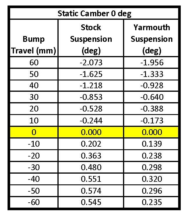
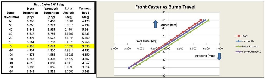
Here are the first results from my analysis of the geometry cycling the suspension through 60mm of jounce and rebound. If you are wondering why I am using metric units all of a sudden, it's because I am using the stock 88' data supplied by my friend Dave (a.k.a Bloozeberry) for comparison and the data was taken in increments of 10mm units. Makes sense right?
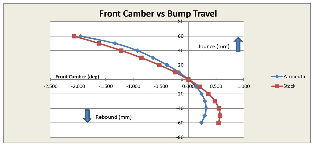
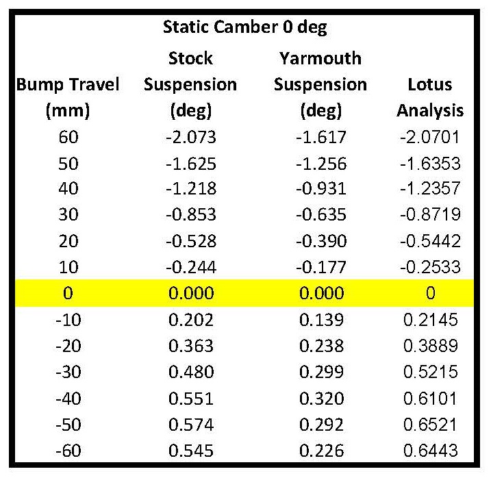
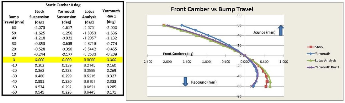
The first graph shows front camber verses bump travel. As you can see, compared to the stock data, my new suspension has slightly less camber change through the range of travel with increased negative camber in jounce and then going slightly positive in rebound.
The first graph shows front camber verses bump travel. As you can see, compared to the stock data, my new suspension has slightly less camber change through the range of travel with increased negative camber in jounce and then going slightly positive in rebound.
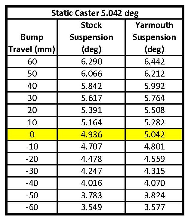
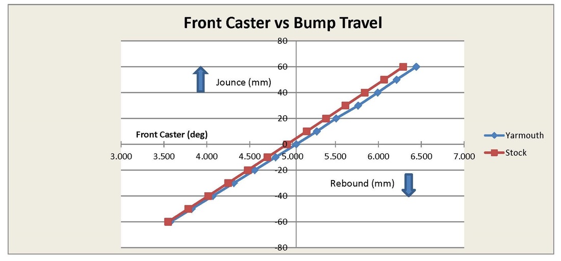
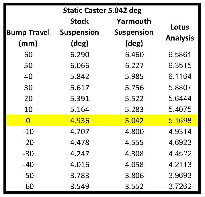
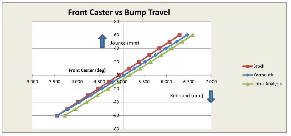
The second graph shows the front caster verses bump travel. The results show that my new suspension is almost identical to the stock suspension with the only difference being a slight shift to the right due to my initial caster being set at 5.042 degrees. It was originally set at exactly 5 degrees but had to be altered slightly to correct for the lowering of the upper control arm described earlier. Still, I am happy with the results of my new suspension so far. There is still lots more suspension analysis to complete.
March 1 2016
Here is a little more of the puzzle regarding the analysis of my front suspension geometry.
March 2 2016
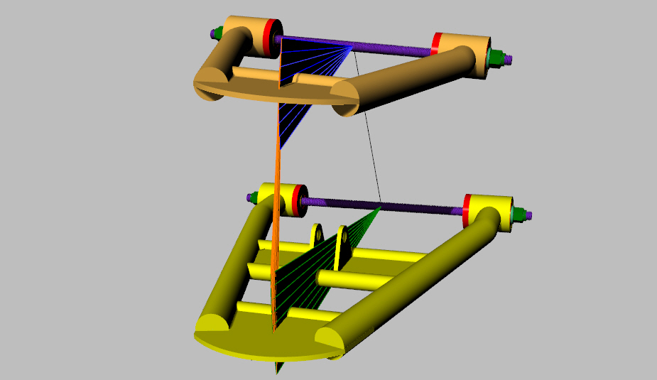
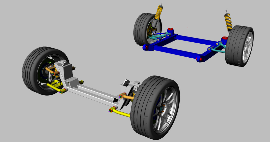
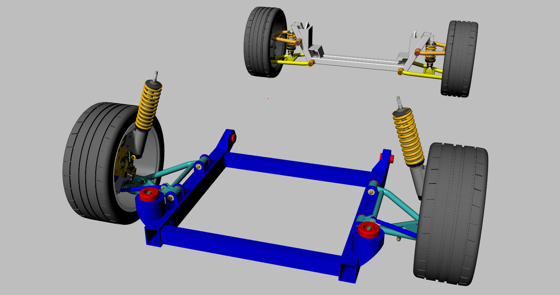
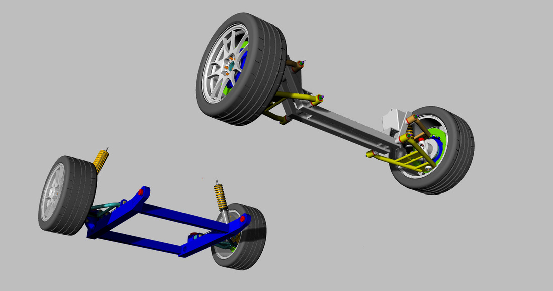
Here are a few images of my front and rear suspension together. I know, I know.....the colors look a little crazy....... but its satisfies my artistic side so please bear with me :)

March 9 2016
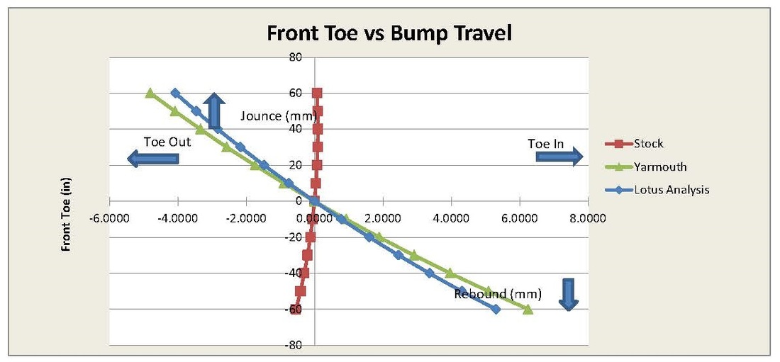
Well, I finally sat down tonight and ran my suspension geometry through jounce and rebound with the steering linkage added so I could calculate my change in front Toe. Adding an additional constraint to the system makes it much more challenging to work with. As you can see, the numbers are not good, compared with the stock data. I'm not sure if this is due to a significant geometry flaw or a mistake taking the data. Since this is a trial and error process, I don't mind posting the " errors". But once I get it figured out, this rogue data will disappear and be replaced with data and suspension geometry that I'm happy with.
March 11 2016
Here are a few images of what is going on to cause the extreme Toe changes due to my suspension geometry.
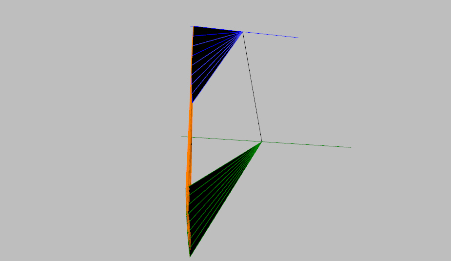
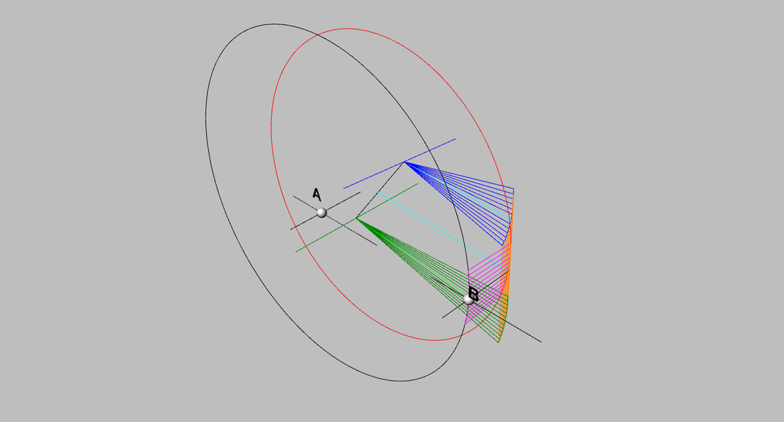
As a starting point, the steering tie rod is assumed to pivot at Point A with the tie rod to be extended to Point B for the wide track. I selected Point B as it in the same vertical and horizontal plane as the steering axis and in the same lateral plane as the king pin axis at static ride height. The end of the tie rod then scribes the radius of the black circle.

With the structure removed for clarity, you can then see the arcs that each linkage and pivot point scribes with each 10 mm change in jounce and rebound shown up to 60 mm in each direction.
The upper control arm scribes the dark blue arc with the light blue being the static ride height
The lower control arm scribes the dark green arc with the light green being the static ride height
The spindle scribes the orange arc.
As the suspension cycles through jounce and rebound, the interface between the steering linkage and the spindle scribes the red arc and the difference between the red arc and the black arc ( the short red horizontal lines) represents the change in toe. So in jounce, spindle arc (red) is outside the steering arc, (black) ( above static point B) so the change in toe is inward ( positive). In rebound ( below static point B) the spindle arc (red) is inside the steering arc (black) so the toe change is outward (negative).
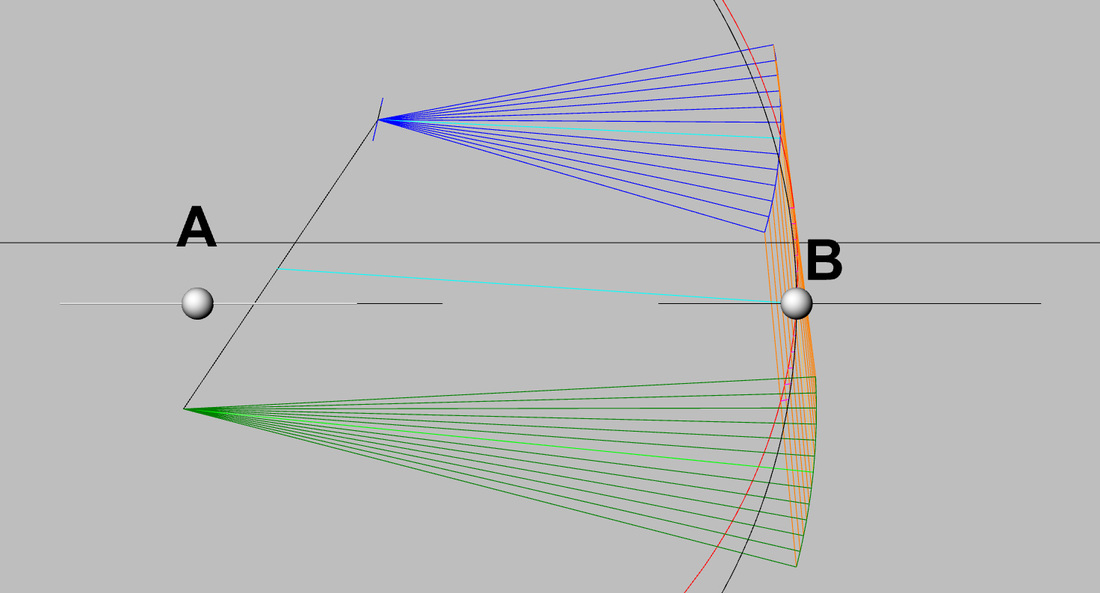
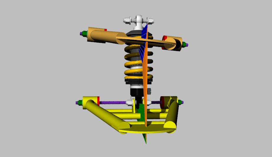
In this view you can see that the spindle arc (red) is smaller and centered at a point midway on the line connecting the axis of rotation of the upper and lower control arms. The steering axis arc ( black) is centered about Point A, the pivot point of the tie rod. It's this difference in axis location and radius that causes the toe to change, causing the spindle to rotate inward or outward about the kingpin axis. As I type this, I realize that I made a error in my geometry. I assumed the tie rod would pivot about point A in a vertical axis through point B, when in fact the tie rod would pivot about A in both planes to follow the spindle motion which is at a plane off vertical due to the tilted axis of the upper control arm. In my results, I allowed the spindle steering arm to stretch in jounce and contract in rebound. Perhaps this is what is causing my results to be exaggerated. I will correct this mistake and record the results. I may also raise point B at the static position to start the motion tie rod higher in the black arc that seems to be closer to the desired red arc of the spindle. In fact, I will locate the tie rod end to be on the same horizontal plane as the intersection of the kingpin axis and the wheel axis when at static ride height. This will mean I have to lengthen the tie rod slightly.
I will correct this mistake and record the results. I may also raise point B at the static position to start the motion tie rod higher in the black arc that seems to be closer to the desired red arc of the spindle. In fact, I will locate the tie rod end to be on the same horizontal plane as the intersection of the kingpin axis and the wheel axis when at static ride height.
April 1 2016
It's hard to believe that 3 weeks have passed since my last update. I apologize for the delay but rest assured, I was not idle on this project. In fact, I have never worked harder at designing and analysing my front suspension design in an effort to improve on the kinematics of the arrangement. Above, you have seen how my camber and caster results have shown a respectable improvement over the stock suspension data. However, I have discovered a significant problem with regard to my front toe change throughout the bump travel of my suspension. Basically, my current suspension arrangement has resulted in a ten fold increase in toe change throughout jounce and rebound....... a condition that is certainly not acceptable. So over the last few weeks I set out to modify my design and correct the problem that I have engineered into my suspension. Well, it has been an exercise in total frustration trying to improve my design. I have altered the location and angles of both the upper and lower control arms as well as moved the steering tie rod, creating almost 20 different scenarios which I have carefully measured, recorded and plotted to 3 decimal places. While I have found slight improvements in camber and caster results, I have been 100% unsuccessful at improving the toe change to any significant amount. I even resorted to moving my steering rack and tie rods to locations which would find them deep inside my front frame rails, a position not even remotely possible to achieve in reality. It has proven to be an exercise in futility. So much so that I even walked away from it for almost a week, at the request of my family who has had to suffer through my late night rantings while sitting in the dark in front of the computer. I have discussed the matter with friends who are much more knowledgeable on the subject of suspensions than I'll ever be, yet I still have come up empty handed.
Last week it got to the point where I was at a stand still. Then my friend Dave suggested I get the design analysed professionally and he has a friend ( Zac Brown) who could run my numbers through his Lotus Suspension Analyser. So I documented all the required datum points and sent them to Zac via Dave. Well, Zac took the time to crunch the numbers and supply me with a very thorough analysis of my design. Thank you very much for your help Zac and Dave. The results are indeed very clear that I have a significant problem with my design. I have plotted the results supplied from the Lotus Analysis and while they do show that my camber and caster are acceptable, my toe change is way out in left field. I'm talking way-y-y-y-y-y out there. :(
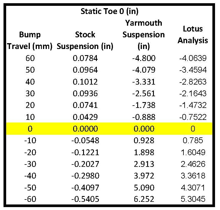
Here are the data tables and graphs of the results. While there is a slight discrepancy between my results and the Lotus Analysis, that is likely due to the fact that my results are actually left over from one of my earlier design iterations where as the results produced by Zac where based on my initial front suspension design which I consider to be my baseline design. I should also note that Zac provided me with much more data on other aspects of my design including Anti-dive and such as well as an analysis of my rear suspension. I'll need some time to digest all the data and plot the results in future posts. So here are the results plotted showing the stock Fiero data, my suspension analysis data and the Lotus Analysis data.

April 3 2016
After spending the entire weekend digesting all the data provided from the Lotus Analysis and reviewing every aspect of my design as well as all the design iterations I have made in an effort to correct the excessive toe change through jounce and rebound, a light bulb suddenly came on in my head.
When I set out in the beginning, I basically designed the front cross member to bolt to the stock chassis locations with the intention that the new control arms I would design would extend out from this structure. I also knew the track width I wanted based on the fender width of the 355 body so I located the wheels, brakes, wheel bearings and spindle with the intention that the spindle and ball joints would locate the outer ends of the control arms. As I wasn't using the stock Fiero front spindle for this project, I designed my new spindle based closely on a drop spindle currently on the market. I then proceeded to design my control arms to span the distance from front cross member to front spindle, using information I sourced regarding control arm angles, kingpin angles and caster angles. I then added the stock Fiero steering rack to the design as it would be needed to do a complete analysis of the suspension. Once all the components were added to the 3D model, I began my analysis of the suspension kinematics. It quickly became evident that I needed to tweek the arrangement and I did so by moving the inboard end of the control arms along the cross member structure. After many attempts to improve the results, it also became evident that I was unable to correct the excessive toe change I was experiencing. I even tried locating the control arm mounts and steering rack mounts in purely theoretical locations in an effort to find some sweep spot that allowed the suspension to work in an acceptable manner........... I could find no such location. It seemed like I was up against a wall with my design. Atleast the Lotus Analysis confirmed what I was measuring for myself using a graphical method.
After many hours looking at every aspect of my design, that light bulb came on........ or atleast I hoped that was a light bulb coming on and not another mini stroke manifesting itself with another blood vessel blockage in my brain. :(
Here is what occurred to me. I had assumed that the front spindle I had designed was suitable as it was based very closely on a drawing on an actual drop spindle currently being produced. "Drop Spindle"??????????? Why the hell was I using a drop spindle? A drop spindle is used to reposition the ball joints in relation to the wheel, thus allowing use of the stock control arms to keep their geometry while gaining an overall lowering effect for the suspension. My control arms are not stock in any sense of the word and thus my ball joints should not be repositioned. By redesigning the front spindle, I could now position my ball joints wherever I wanted, allowing more freedom to position the various suspension components. So I set out to raise both upper and lower ball joints about 1" higher on my spindle and reconfigured the control arms so that the inner ends were located along an axis that also passed through the outer end of the steering rack pivot ( ie: inner end of the tie rod pivot).
At this point, I have only drawn the new suspension geometry in wire frame format so that I could conduct the analysis easily. Here are the results, labeled as Yarmouth Rev 1.
The Camber vs Bump Travel graph shows that the arrangement is an improvement on the stock geometry, especially in rebound.
The Caster vs Bump Travel graph showed that the arrangement basically maintained the stock geometry results.
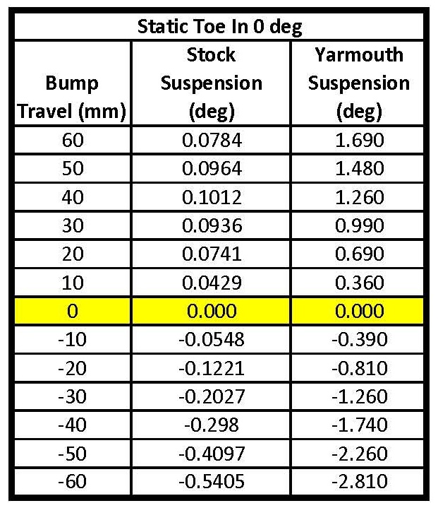
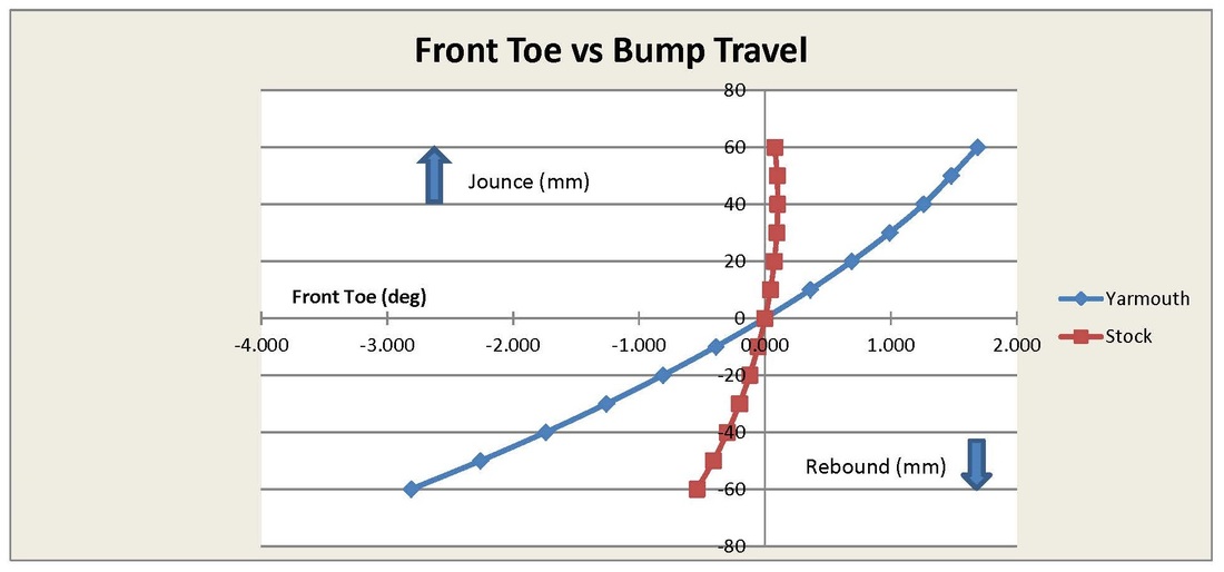
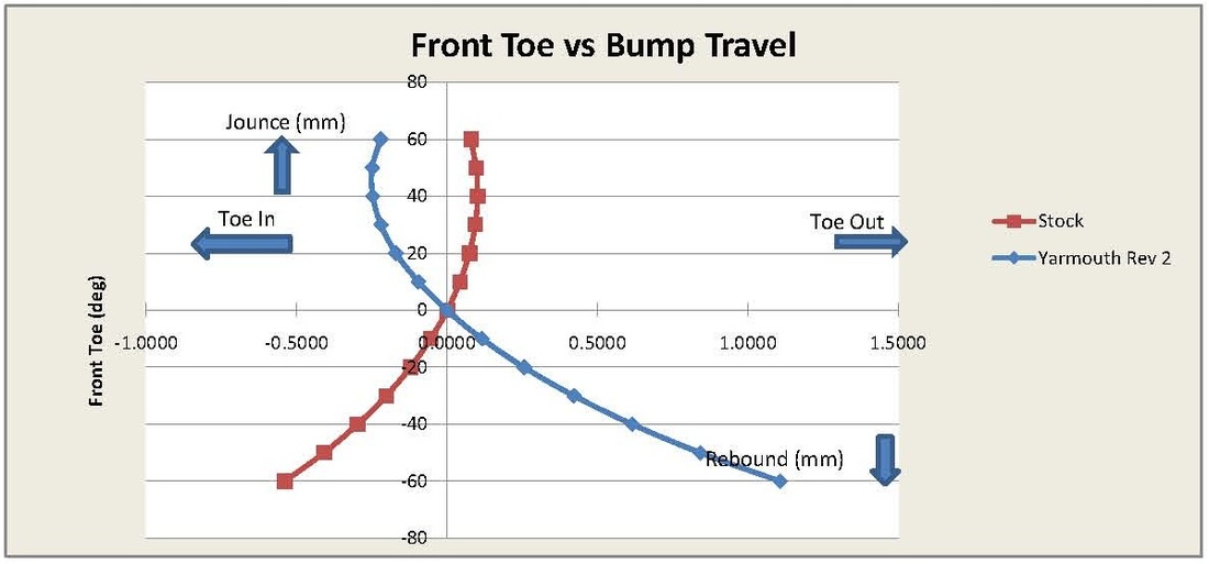
The Toe vs Bump Travel graph shows the most significant results improvement. I think the results are quite satisfactory but I think I can still tweek the suspension geometry a little more to minimize the toe change even further.

If I remove the data from my first design attempt and the Lotus data, the graph focuses in on the stock data and the Yarmouth data Rev 1. The Toe change has be reduced to less than 1/4" degree in full jounce and just over 1 degree in full rebound. This is a huge improvement in the results and the now gives me the confidence to proceed ahead with fabrication of the front cross member. Once I have the geometry tweeked to give the best results, I'll start fabrication of the spindles and control arms.
Dave
Looking forward to seeing your new front suspension layout now that you've solved the toe issue. Good to see a breakthrough on this bug-bear.
Graham
Thanks Dave I still have a little tweeking but its all at the spindle now. I have all the aluminum for the front cross member so it's time to start cutting and fitting...........finally :)
