mirrors
The first items that I plan to construct for the exterior body are the two mirrors. My goal is to make a foam plug from which I can make a mould of. From here I plan to vacuum infuse carbon fiber. I plan to make mirrors so that they can fold back to help prevent damage when backing into the garage. The 355 mirrors stick out quite far in order to see around the wide rear end. For the finishing details, I plan to make the mirrors power operated.
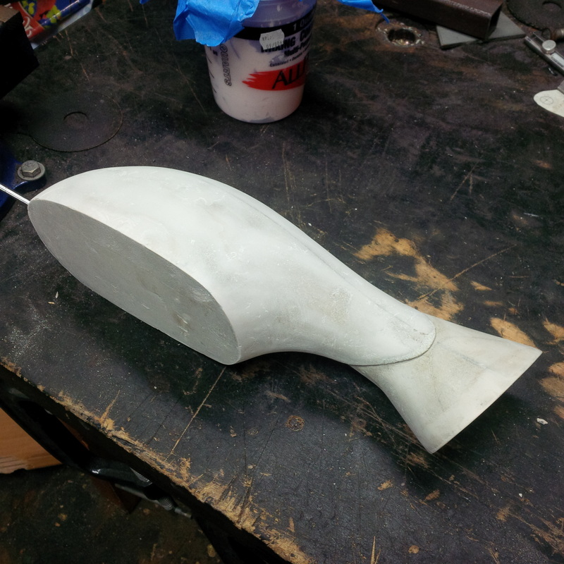
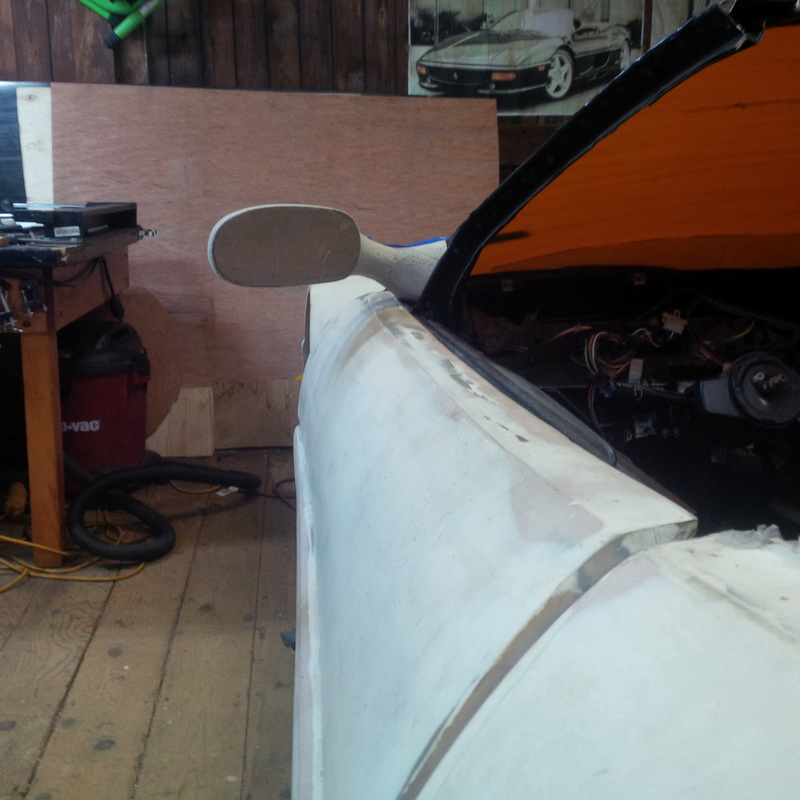
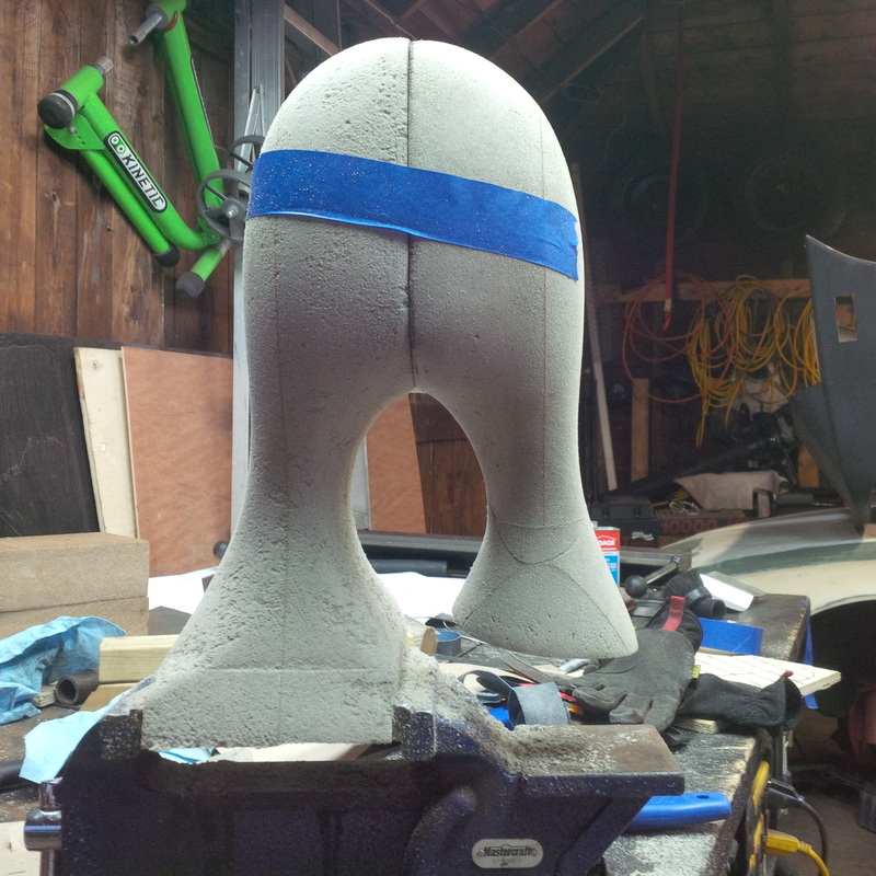
Here are a few pictures of the driver side foam plug in its infancy with the basic shape roughed out. Like the car body itself, the 355 mirror has an elegant flowing shape to it.
Here are a few pictures of the driver side foam plug in its infancy with the basic shape roughed out. Like the car body itself, the 355 mirror has an elegant flowing shape to it.

|
|
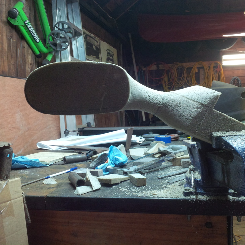
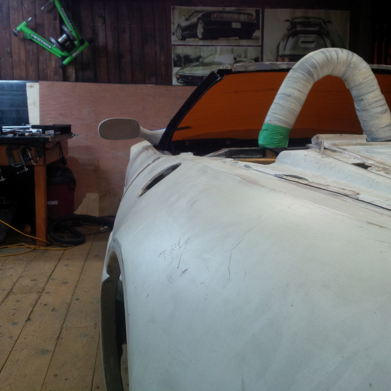
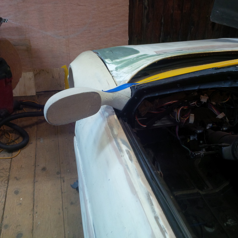
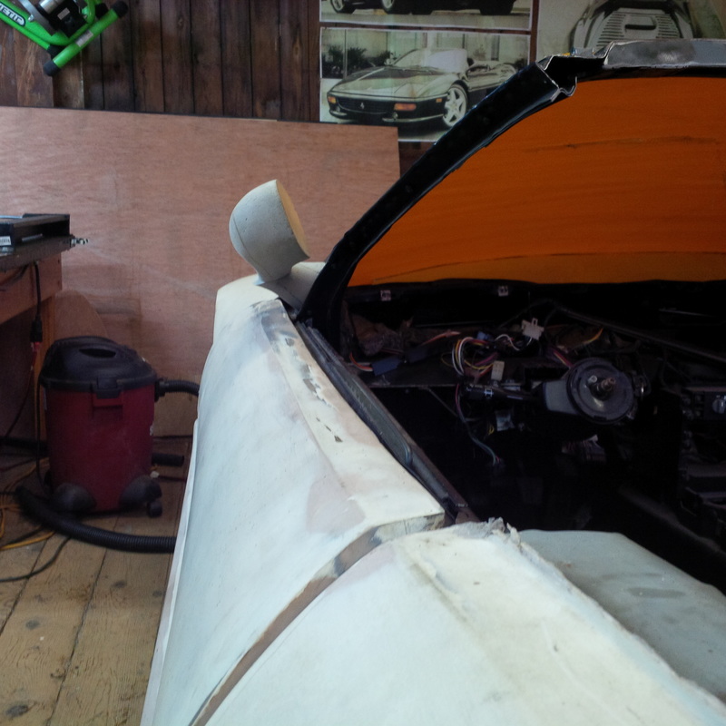
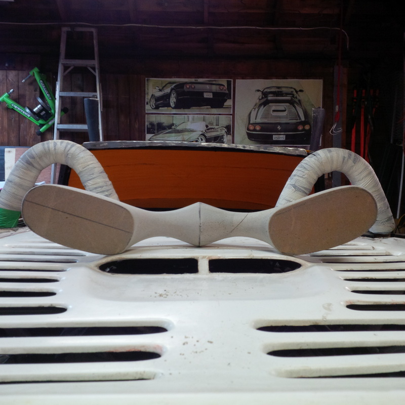
Continuing with the shaping process, I refine the shape further and set the angle of the mirror relative to the chassis. It is a challenge to form the mirror to get a smooth flowing shape that is not too bulky yet not so thin that is lacks strength and doesn't match the bulk of the overall car. Here are a few pictures of the mirror body in position. I think it still needs to be slimmed down slightly where it attaches to the chassis.

|

|
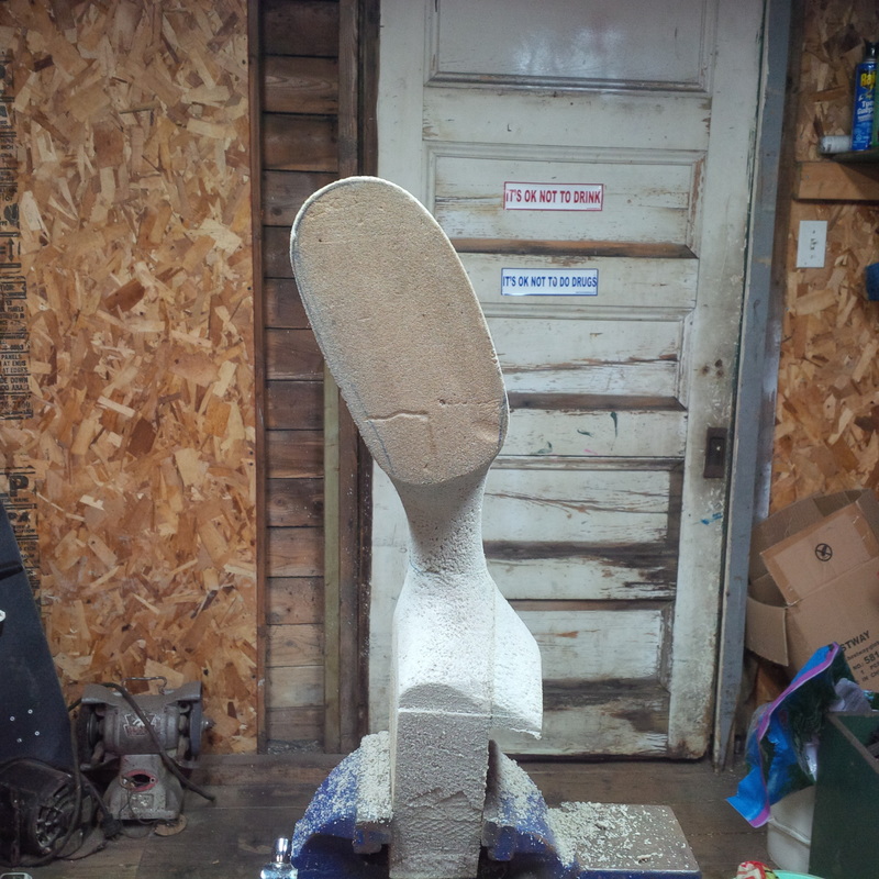
Now begins the process of making the passenger side mirror foam plug which of course is a mirror image of the driver side. This is a challenge to recreate the mirror image of such a smooth flowing form. But as always, you start by roughing in the general shape. The key to remember is that the shape I desire is hidden inside that foam block. I just need to remove the excess material to expose the object residing inside.
Sept 29 2015
The shape is getting closer now. The final sanding will bring the shapes in line with each other.
The shape is getting closer now. The final sanding will bring the shapes in line with each other.

|

|
Almost a perfect mirror image of each other now.
|

|
Nov 8 2015
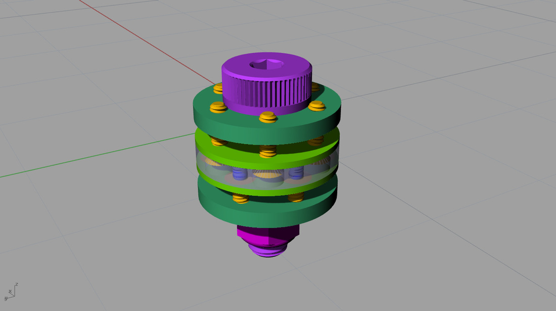
I have been giving much thought to the mechanism that will allow the mirror to pivot in a controlled manner yet be robust enough to hold it in place while driving. Here is the current design of such a mechanism.
I have been giving much thought to the mechanism that will allow the mirror to pivot in a controlled manner yet be robust enough to hold it in place while driving. Here is the current design of such a mechanism.
|
|

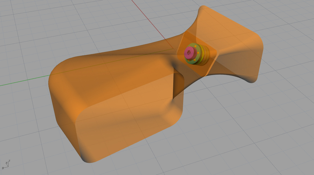
The idea behind this mechanism is such that the mating flanges of the movable mirror body and stationary mirror mounting base are clamped between the upper and lower dark green and light green rings respectively. They are secured through the mirror body material ( frp or carbon fibre) using the gold machine screws. A UHMW disk ( light blue) is placed between the mirror half and the mounting body half and is secured to the movable mirror end with the longer gold machine screws. Located in pockets in this disk are a series of steel balls and springs so that when the mechanism is assembled, the balls will be pressed into the torx heads of the mirror mounting screws. The whole mechanism rotates about the purple shoulder bolt and as the parts rotate relative to one another, the balls will push against the springs and then drop down into the next torx head. With 6 torx heads as shown, the mirrors will index 60 degrees increments between each torx screw head. The resistance to rotate from position to position will be set by the spring rate pushing on the balls. I can leave some balls out to reduce the resistance is necessary. The various components are ordered and I will build the mechanism soon and test my design.
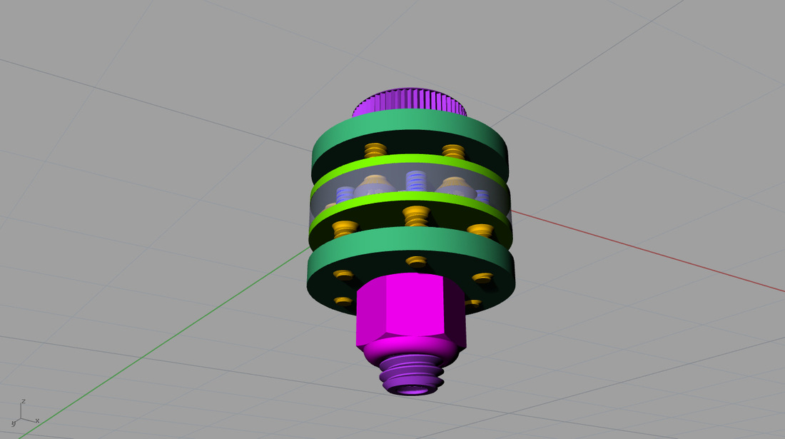
Here are a couple images of the mechanism fitted to a very crude mirror drawing to demonstrate where it will be located.
Here are a couple images of the mechanism fitted to a very crude mirror drawing to demonstrate where it will be located.

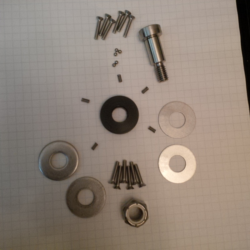
Here are all the parts needed to build one mechanism as designed. Now its time to build it and see how it works.
Dec 12 2015
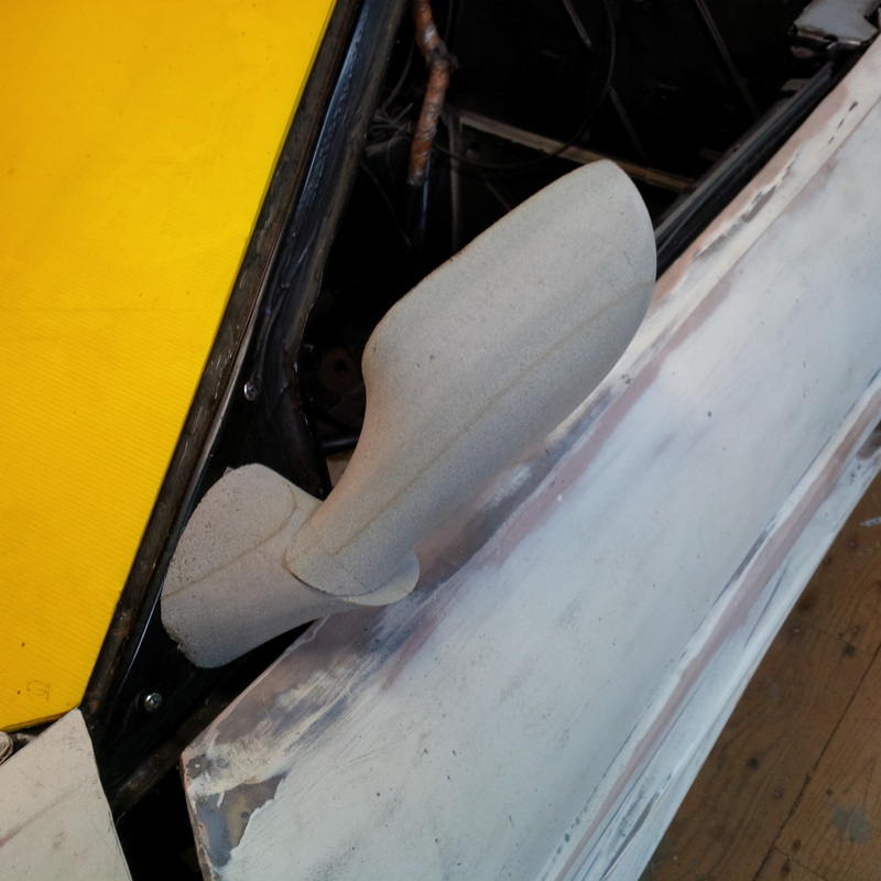
Here is the driver side mirror foam plug after a coat of Poly-Fair F26 putty and sanded back. It's ready to be sprayed with a thin coat of sandable gelcoat and then lots more sanding prior to splashing a mould off it. The passenger side foam plug is ready for putty now too.
Here is the driver side mirror foam plug after a coat of Poly-Fair F26 putty and sanded back. It's ready to be sprayed with a thin coat of sandable gelcoat and then lots more sanding prior to splashing a mould off it. The passenger side foam plug is ready for putty now too.