Intake Manifold Reversal
May 6 2017
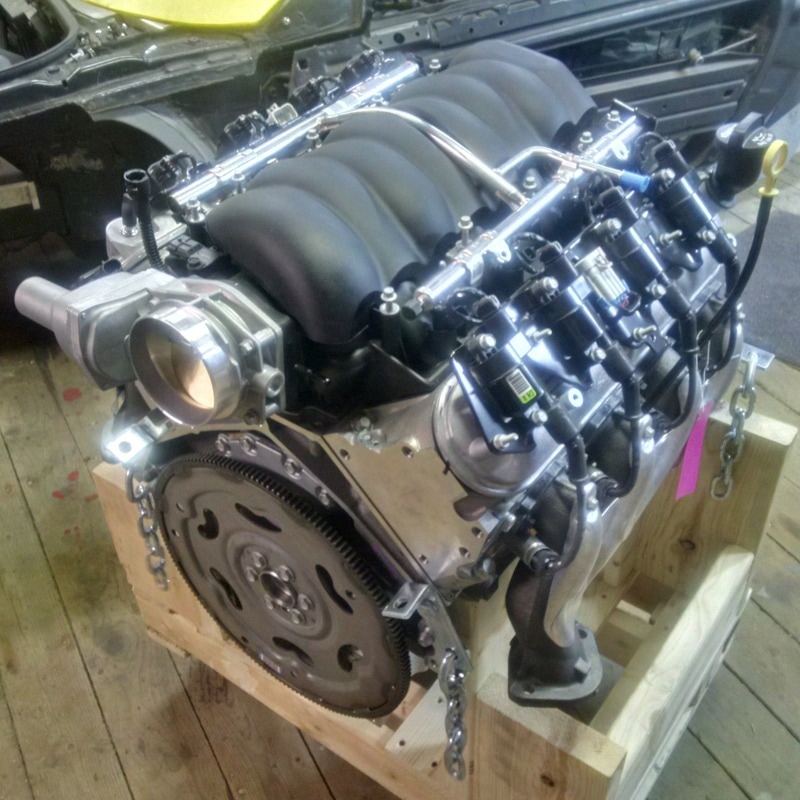
With my plans to installed the engine as close to the back of the firewall as possible, it has always been apparent that the intake manifold of my new engine was going to have to be reversed 180 degrees so that it would be facing the rear of the engine. This would allow plenty of room for some type of intake plumbing and air filter arrangement in the future.
The LS3 has a symmetrical intake manifold so that no matter which way it was facing ( forward or rearward), the ports of the intake would always align with the intake ports on the cylinder heads. The same holds true for all the hardware and fasteners that hold the intake manifold in place. This is not to say that there are not a couple of issues regarding auxiliary equipment that will have to be addressed prior to the intake reversal being completed and I have researched this extensively prior to purchasing the engine so I had a fairly good idea of the challenges that lay ahead. I will make every effort to document this process as there are a number of different solutions possible, most of which you can find on the internet.
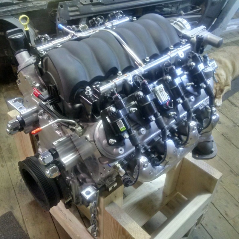
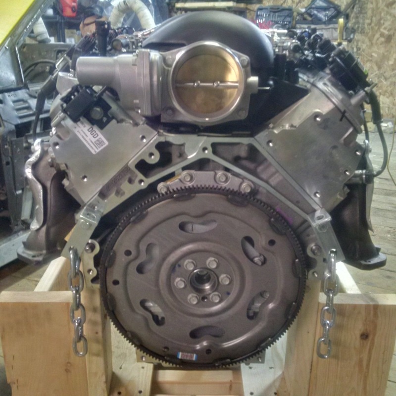
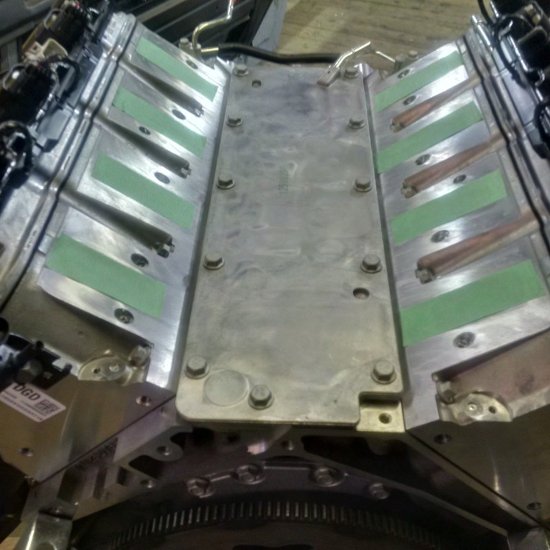
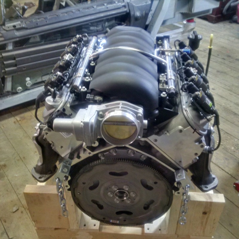
Here are a couple images of the engine with the intake reversed temporarily for now. I have to apologize for the poor quality of my pics lately. It seems this new engine is just too damn shiny to photograph properly. In Yarmouth NS, we call those "Y-Town Problems" :)
May 7 2017
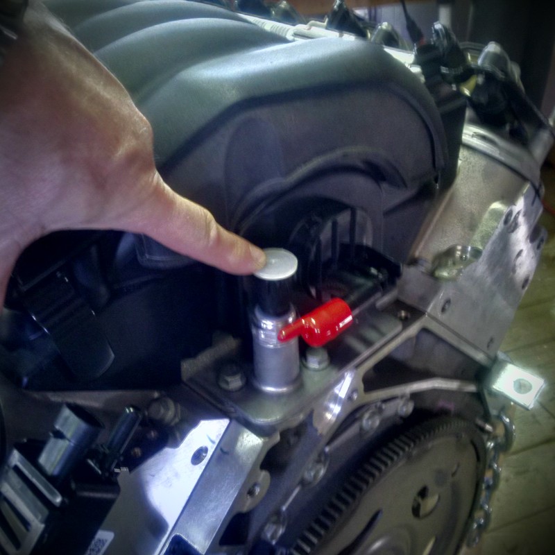
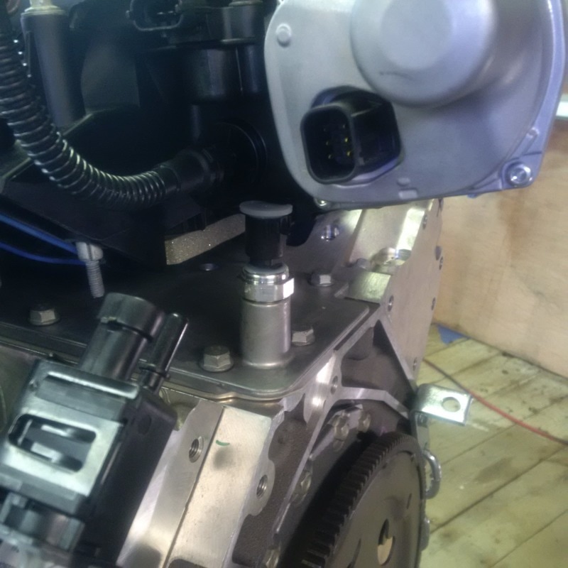
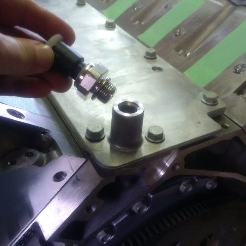
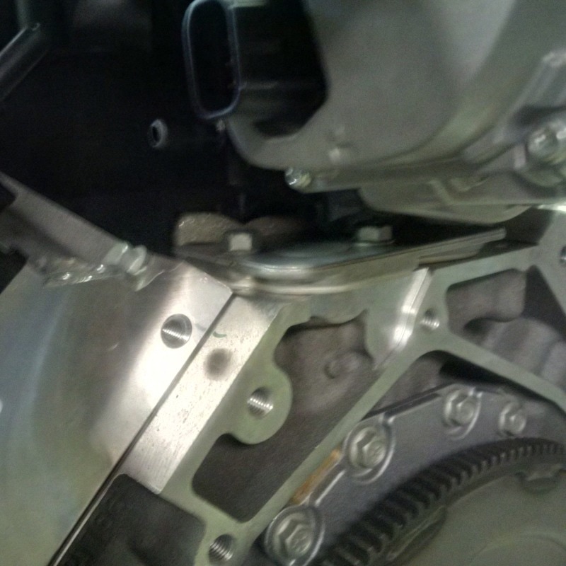
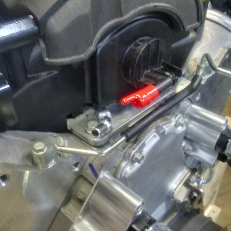
While the pictures above makes it appear that it's a simple matter to reverse the intake manifold, the truth is there is a little matter involving the oil pressure sending unit that is located at the rear end of the lifter valley cover. In the stock position, the intake manifold has been designed to miss the sensor. But when you reverse the intake manifold, it lands directly on the sending unit. Here is the sending unit at the rear of the engine.
While the pictures above makes it appear that it's a simple matter to reverse the intake manifold, the truth is there is a little matter involving the oil pressure sending unit that is located at the rear end of the lifter valley cover. In the stock position, the intake manifold has been designed to miss the sensor. But when you reverse the intake manifold, it lands directly on the sending unit. Here is the sending unit at the rear of the engine.
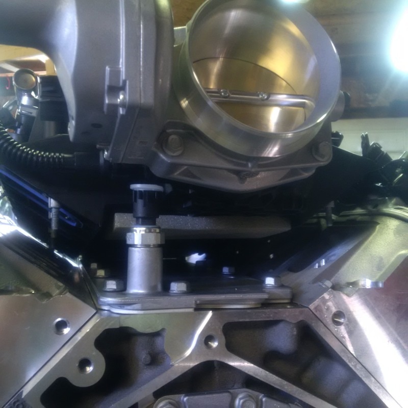
And here is the sending unit with the intake reversed.
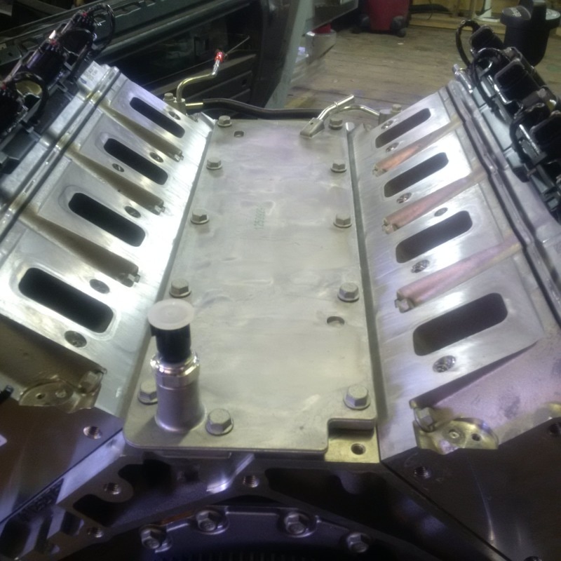
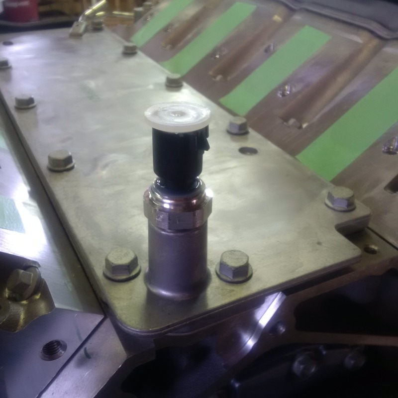
Here is the lifter valley plate with the intake manifold removed.
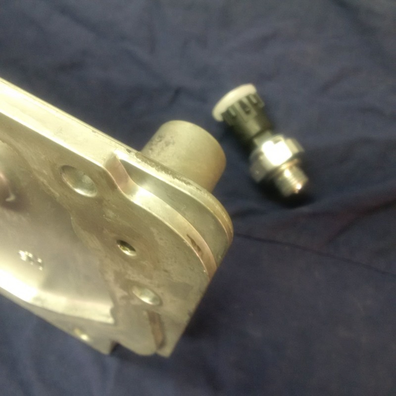
At this point, there are a number of solutions available, most of which involve removing the sensor threaded boss flush with the plate and bolting on a custom machined boss which turns the sensor on its side. A search of the web reveals that while a number of people have had success with this, most indicate that it may be likely that the underside of the intake manifold will still be against the modified boss and thus it will be necessary to grind away some of the plastic structure on the underside of the intake manifold as well. The other solution is to remove the boss altogether and plug the remaining hole. Then relocate the sensor to another location on the engine. That is the plan I have in mind so once the new adapter for the relocation of the sensor arrives, I'll show you in detail how I will deal with this issue.
May 8 2017
Here is a generic drawing of the oil lubrication system of the LS3 engine. You can see the oil pressure sending unit at the top of the engine where the clean pressurized oil starts its distribution to the rest of the engine. Down below at the filter housing, you can see that the pressured oil leaves the filter and passes through an inlet and outlet port before proceeding upward. The stock engine comes with a blank plate across these ports allowing the oil to pass though. This plate can be replaced with a diverter block to redirect the clean pressurized oil to and from a remote oil cooler if so desired. It is also an ideal place to tap into the pressurized oil supply for other things like additional pressure / temp sensors or even be used as a source lubrication oil for fun things like turbo chargers.
Here is a generic drawing of the oil lubrication system of the LS3 engine. You can see the oil pressure sending unit at the top of the engine where the clean pressurized oil starts its distribution to the rest of the engine. Down below at the filter housing, you can see that the pressured oil leaves the filter and passes through an inlet and outlet port before proceeding upward. The stock engine comes with a blank plate across these ports allowing the oil to pass though. This plate can be replaced with a diverter block to redirect the clean pressurized oil to and from a remote oil cooler if so desired. It is also an ideal place to tap into the pressurized oil supply for other things like additional pressure / temp sensors or even be used as a source lubrication oil for fun things like turbo chargers.
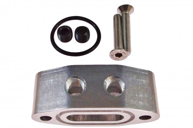
I have ordered a diverter block from ICT Billet that has been fitted with a 16M x 1.5 threaded port in the bottom to accept the stock oil pressure sending unit. It also has two (2) 1/8" threaded ports on the top to accept additional sending units for oil pressure and temperature or perhaps two pressure supplies for future twin turbos :o I really don't see that happening but I do have plans to maybe install a virtual engine monitoring panel in the engine bay so that you can see engine operating parameters like pressure and temperatures, rpms etc. Perhaps a digital display like we often install on ships we build.
May 9 2017
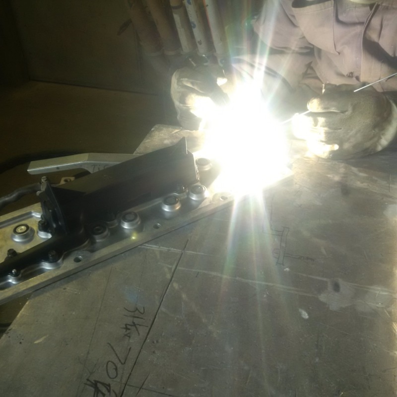
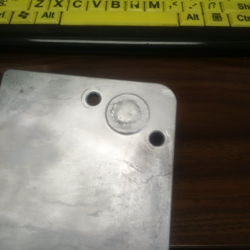
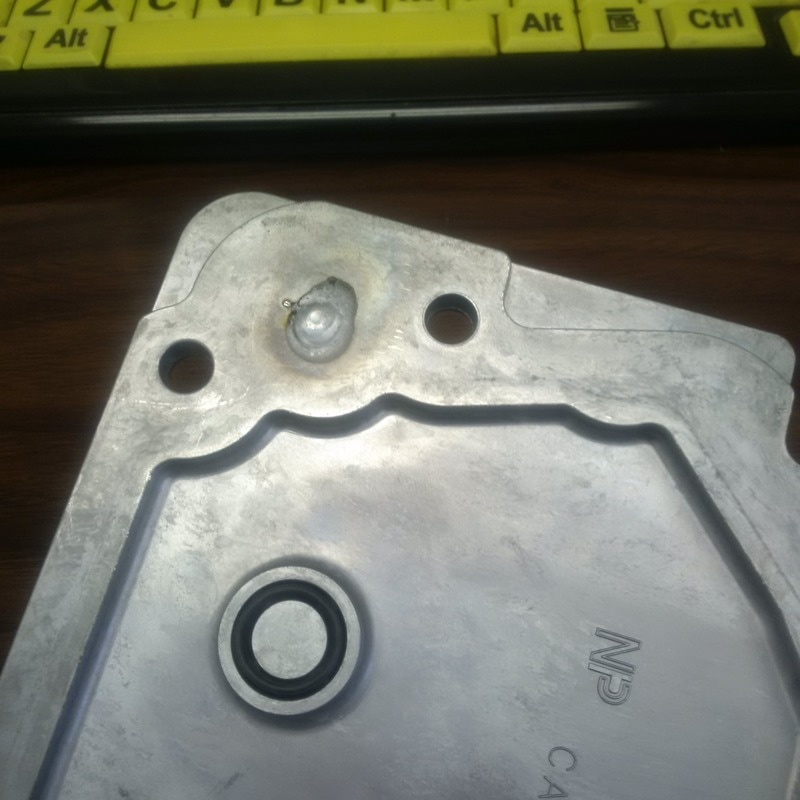
As I had mentioned above, the first step to reversing the intake manifold is to remove the oil pressure sending unit boss from the lifter valley cover plate. A couple seconds in the bandsaw and the boss was history. Then a quick TIG welding inside and out on the cover plate and the factory hole was history as well. Now it just needs a quick sanding to get the surfaces smooth and it will be ready to go back on the engine.
As I had mentioned above, the first step to reversing the intake manifold is to remove the oil pressure sending unit boss from the lifter valley cover plate. A couple seconds in the bandsaw and the boss was history. Then a quick TIG welding inside and out on the cover plate and the factory hole was history as well. Now it just needs a quick sanding to get the surfaces smooth and it will be ready to go back on the engine.
This evening I filed down the high spot left by the tig welder and then bolted the lifter valley cover down to the required torque. I left a very slight boss so it would be easier to file down the weld without running the file over the surrounding plate. Once it was secured in place, I installed the intake manifold in the reverse configuration and torqued it down to GM spec. As you can see, there is lots of clearance under the front of the intake and the PCV pipe in the rear of the lifter valley plate easily clears the intake at that end.
May 15 2017
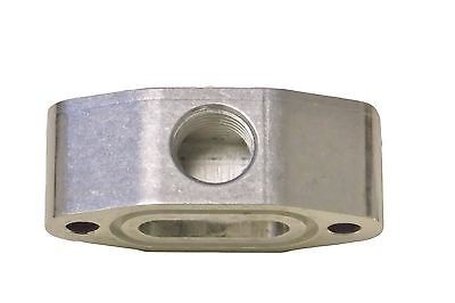
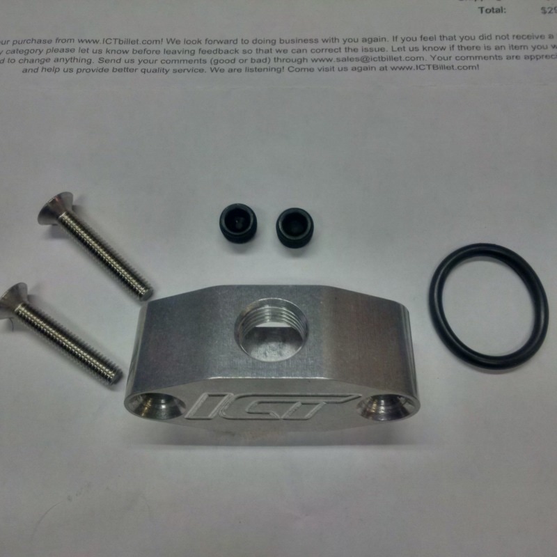
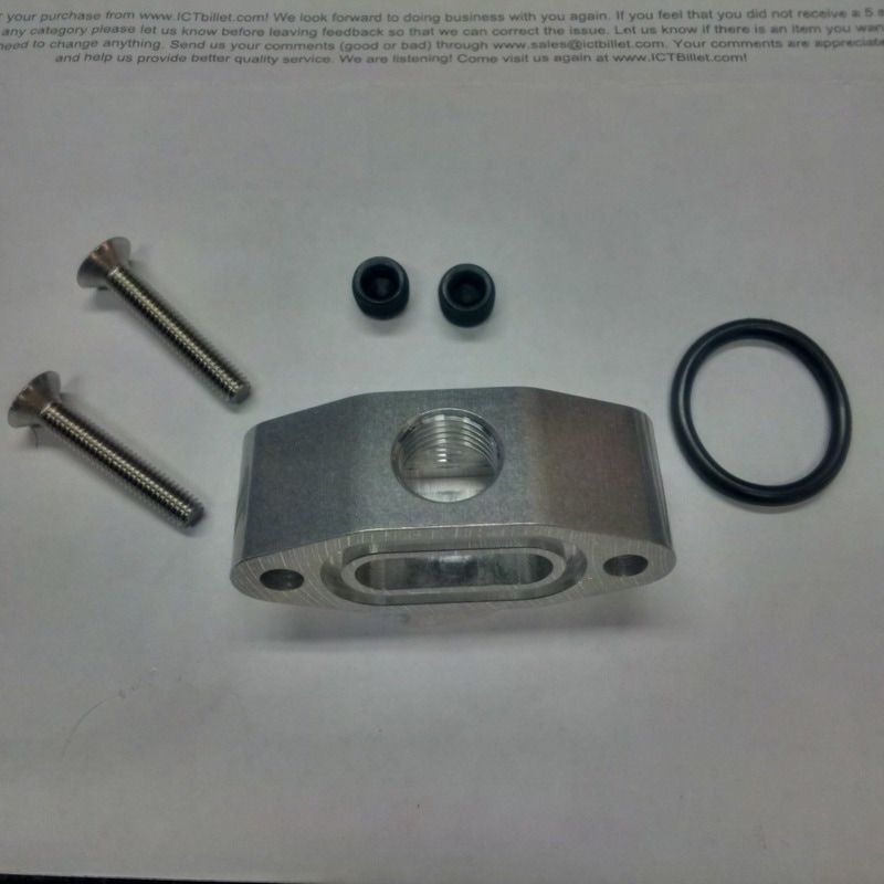
To wrap up the final item relating to the reversing of the intake manifold, the oil pressure sending unit that was removed from the lifter valley cover plate is to be fitted at an alternative location on the oil filter housing. As noted above, I ordered an adapter from ICT Billet made specifically for this purpose. The part arrived today in a timely manner and here is what they supplied. The parts are high quality and they even changed the design slightly by putting the connection for the sending unit on the top so it does not hang down in front of the oil filter.
To wrap up the final item relating to the reversing of the intake manifold, the oil pressure sending unit that was removed from the lifter valley cover plate is to be fitted at an alternative location on the oil filter housing. As noted above, I ordered an adapter from ICT Billet made specifically for this purpose. The part arrived today in a timely manner and here is what they supplied. The parts are high quality and they even changed the design slightly by putting the connection for the sending unit on the top so it does not hang down in front of the oil filter.
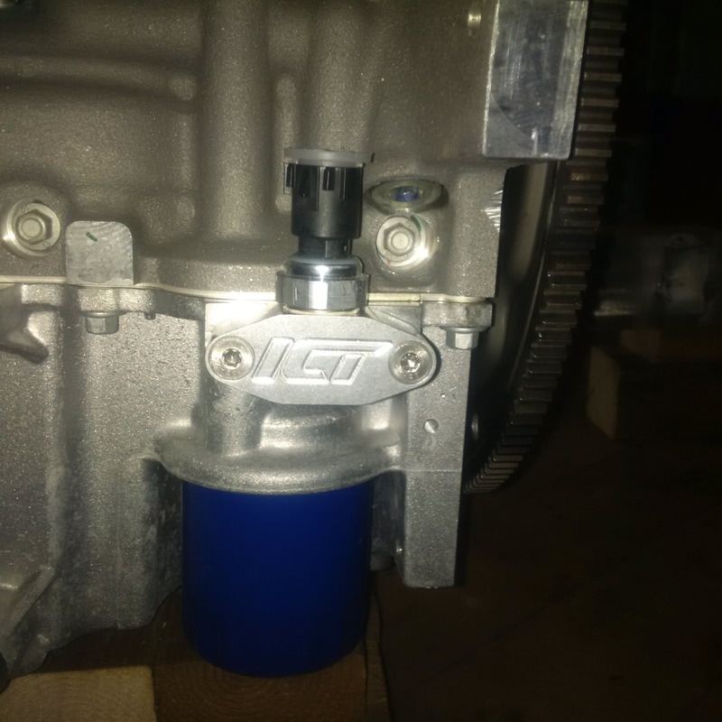
Here is the final product with the new ICT Billet bypass adapter installed with SS bolts and the oil pressure sending unit installed in the vertical position. Its a functional and good looking solution and the only other adaptation required will be to extend the factory OEM wiring harness to reach the new location of the sending unit plug. That is a job for a future post.
November 24 2017
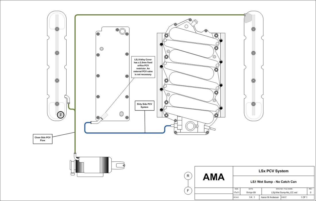
One of the other issues associated with reversing the intake manifold that I had not finalized, was the modification to the PCV plumbing, specifically, the dirty side of the system. As you can see from the drawing below ( drawing credit: Aaron Anderson), the dirty side of the PCV system (blue line) includes a short hose that connects the vent spigot on the top forward end of the lifter valley cover to a spigot on the passenger side of the intake manifold just behind the throttle body. This allows the intake to draw oil fumes off the top of the block and into the intake.
There are many after market options available to pass these fumes through a catch can prior to entering the intake to help reduce the chance of oil pooling in the intake. This crate engine didn't come with such a system and for now, I have no plans to install a catch can system. So I am left with the task of rerouting this plumbing since the throttle body spigot is now at the rear of the engine because I reversed the intake.
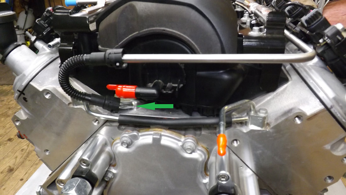
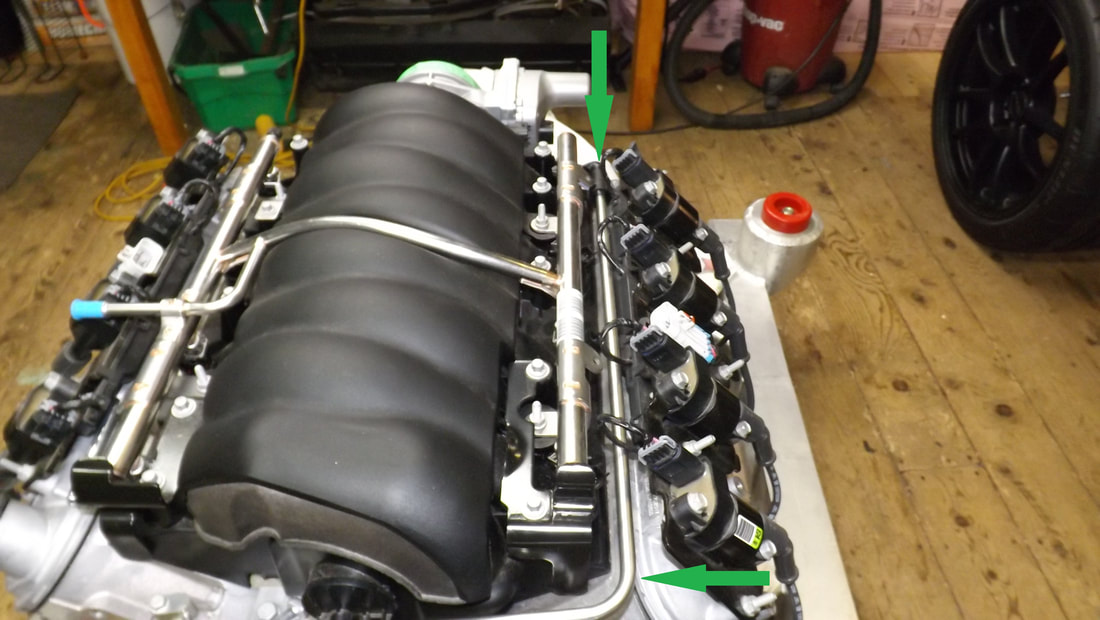
My plan is to use the stock PCV hose that came with the engine to connect the spigot on the lifter valley cover to a length of 3/8" x 0.035" stainless steel tubing which I will run just under the passenger side fuel rail from the front of the engine to the rear of the engine, including a 90 degree bend around the back side of the intake manifold to the throttle body spigot. On the back end of the tubing I will fit a second short length of stock PCV tubing ( ordered from the local GM dealer) that will connect the SS tubing to the spigot. The stock PCV hoses have clips at both ends that secure them to the spigots and the 3/8" tubing is a perfect snug fit inside the other ends. I may crimp a tube fitting olive on each end of the SS tubing for the PCV clips to hold on too even though they fit quite snug without them. I will fabricate a couple clips to hold the SS tubing secure under the fuel rail but above the rocker cover.
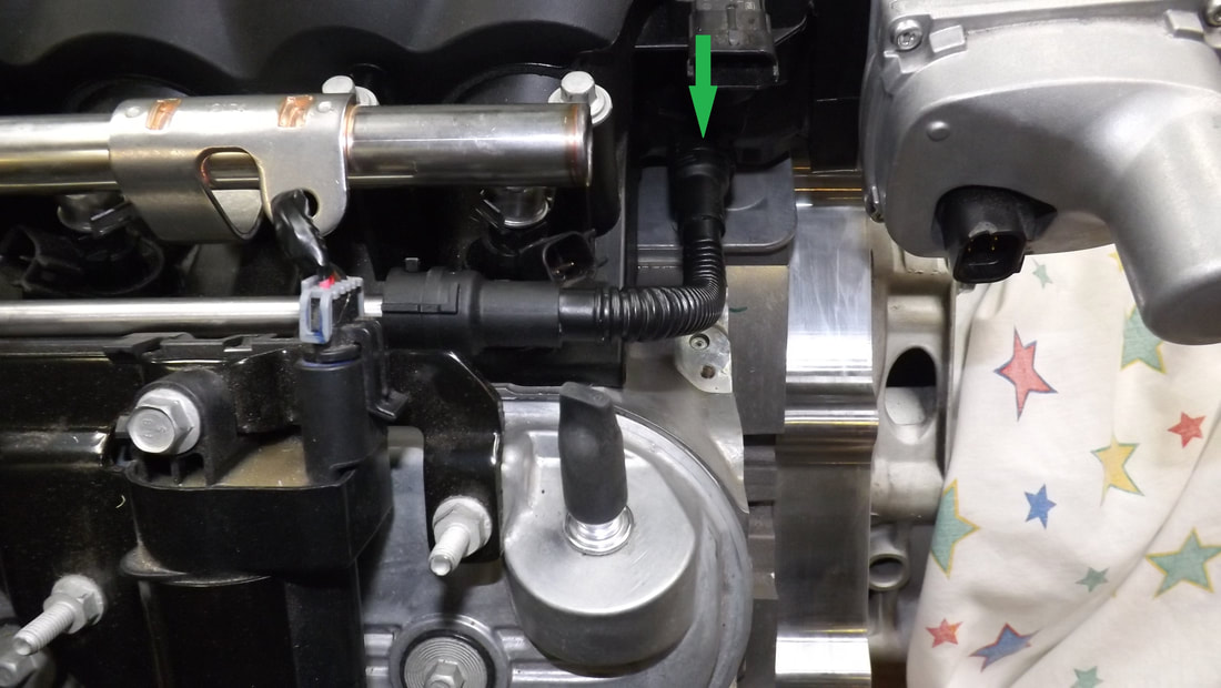
Here are pics of the lifter valley spigot end and the throttle body spigot end with the PCV hoses and SS tubing in place. The third image shows the tubing running under the fuel rail. See green arrows.
You will also notice on the PCV system drawing above that there is also plumbing required for the clean side of the system. Both rocker covers have spigots available for this, however, I will leave that for now until I have the engine intake plumbing figured out so that I know exactly where I will tap off for the clean air supply.
