steering
March 7 2016
If you have been following the development of my front suspension design, you`ll notice that I have added the stock steering rack to my 3D model. My plan is to use this equipment as it has got very low miles on it and its still in mint condition. I have added suitable mounts to my new front cross member to suit the use of the stock steering rack and for now I`ll leave it in that location. Since my front cross member is a different construction and geometry than the stock front cross member, it`s quite likely I will have to alter the length of the steering shaft. I`ll deal with that in the future.
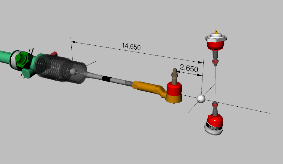
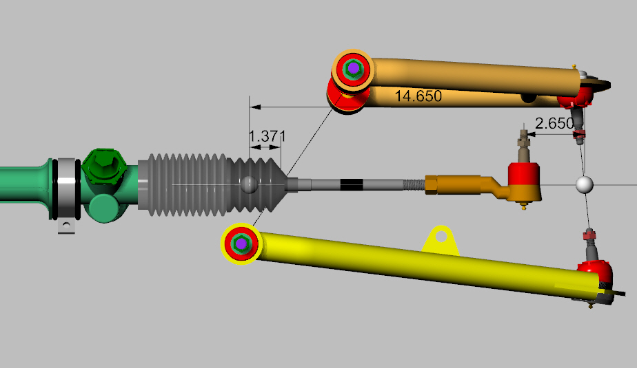
For now, I have identified the basic geometry of the stock rack and measured how much longer the tie rod ends will have to be extended to reach the new front spindle design. (keep in mind I have widened the front track of the car). From my drawing, I estimate that I will have to extend the tie rods by about 2.65 inches. This gives an effective tie rod length of about 14.65 inches. This will put the axis of the tie rod in line longitudinally and horizontally with the king pin axis. Again, since I didn`t take the dust boot off the tie rod shaft, I estimated where the inboard pivot of the tie rod was.
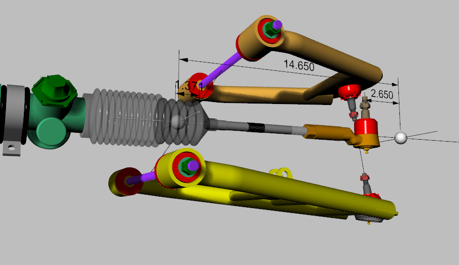
Looking strait on to the steering rack, this puts the tie rod pivot about 1.37 inches inboard of the axis that runs through the pivot axis of the upper and lower control arms. As I am trying to minimize bump steer in my new design, the closer all the pivot axes are in a straight line, the more successful the design should be at minimizing bump steer. I`ll conduct an analysis of the suspension geometry based on this arrangement and measure bump steer through jounce and rebound in a manner similarly used for my caster and camber measurements. Fingers crossed.
Because most of the components don`t lie in a common plain ( that would be too easy) it`s difficult to show the arrangement in any one view. I find picking a random viewing angle that feels like it shows things clearly is the only option. If I ever get to the point where I decide to register my own domain name, I`ll have the option to post videos of my design, allowing the assembly to slowly rotate as if you are walking around it. Its a very interesting way to show a 3D model like this, especially if you suddenly have an ah-ha moment and you pause the video at a particular perspective.


