Rear sway bar
Jan 31 2015
During the design process of my rear suspension and engine cradle, I gave consideration to the use of a rear sway bar to further improve of the performance of the car handling. I say " gave consideration" because at this stage of the build, there are many aspects of the construction that are still up in the air. One fact was obvious, the sway bar would likely be a custom unit designed to suit the arrangement of my rear geometry. After researching the topic, it seemed the likely way to install a sway bar would be to build it from components to get the performance I desired. Without getting to deep into the sway bar design at this stage, I decided to pick a basic geometry that could be built from off the shelf components and then lay out an arrangement that would hopefully fit my rear suspension when the time came to build it.
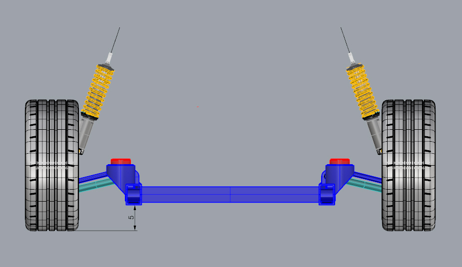
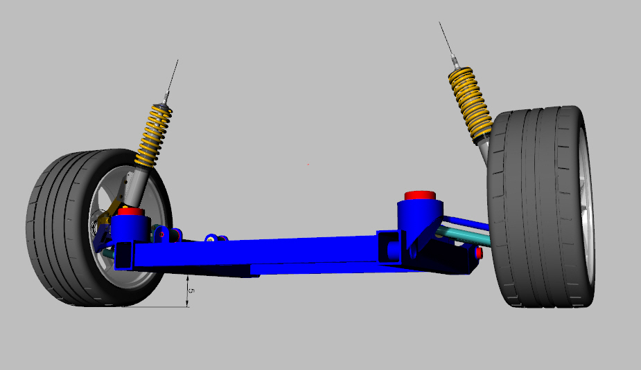
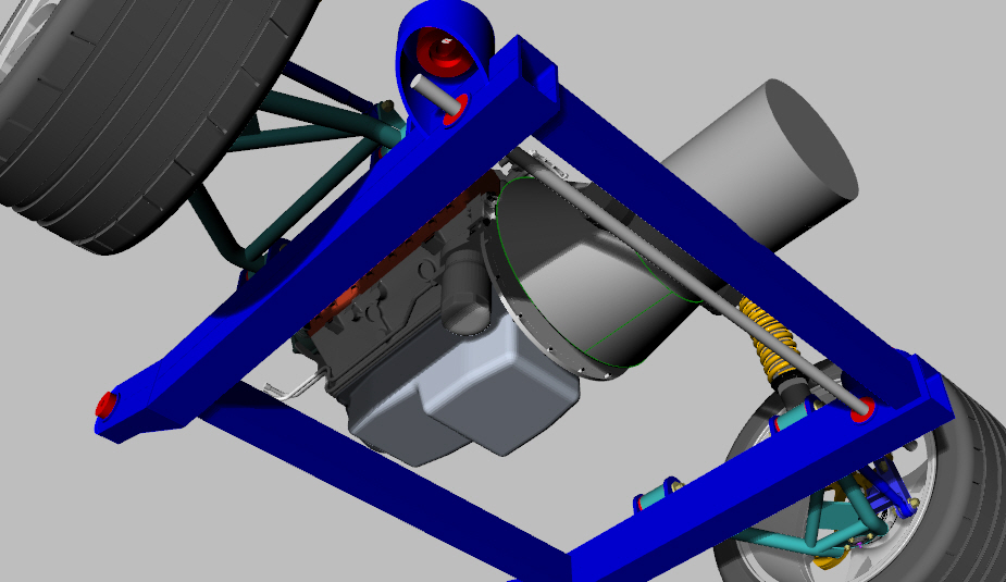
Since I knew the new track width of my rear suspension and the design of my rear control arms, it was then just a simple matter of identifying a suitable clear path from one side of the car to the other side. When designing my new engine cradle, I decided to keep the longitudinal rails as low as possible so that they would not interfere with the engine, gearbox and drive line components. In fact, the bottom edge of the cradle will be one of the lowest parts of the car, giving a 5" ground clearance.
During the design process of my rear suspension and engine cradle, I gave consideration to the use of a rear sway bar to further improve of the performance of the car handling. I say " gave consideration" because at this stage of the build, there are many aspects of the construction that are still up in the air. One fact was obvious, the sway bar would likely be a custom unit designed to suit the arrangement of my rear geometry. After researching the topic, it seemed the likely way to install a sway bar would be to build it from components to get the performance I desired. Without getting to deep into the sway bar design at this stage, I decided to pick a basic geometry that could be built from off the shelf components and then lay out an arrangement that would hopefully fit my rear suspension when the time came to build it.
Since I knew the new track width of my rear suspension and the design of my rear control arms, it was then just a simple matter of identifying a suitable clear path from one side of the car to the other side. When designing my new engine cradle, I decided to keep the longitudinal rails as low as possible so that they would not interfere with the engine, gearbox and drive line components. In fact, the bottom edge of the cradle will be one of the lowest parts of the car, giving a 5" ground clearance.
|
|
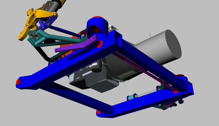
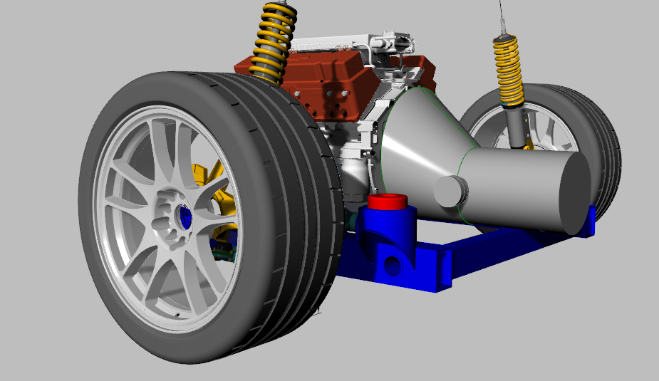
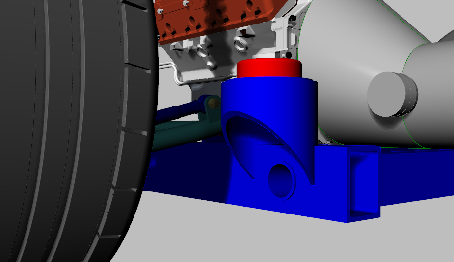
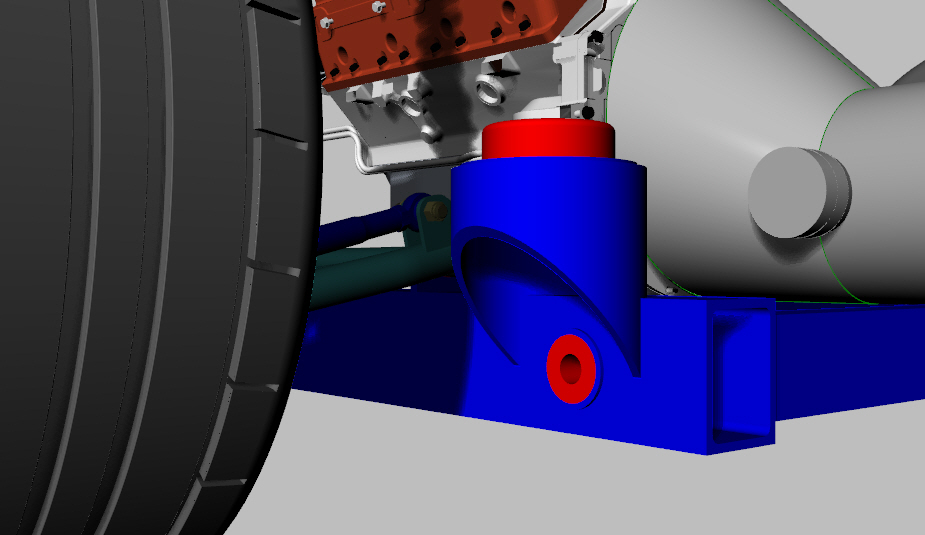
With the engine cradle being so low, I decide that the sway bar would have to either pass over the top of the cradle or pass through it somehow. As I have noted, my plan is to install and LS1 longitudinally with an Audi 6 speed gearbox. In lieu of a proper mechanical drawing of the actual gearbox, I drew in a basic gearbox shape based on measurements available online and from other project car friends. It became quite clear that the sway bar would not be able to pass over the engine cradle due to the low mounted gearbox.
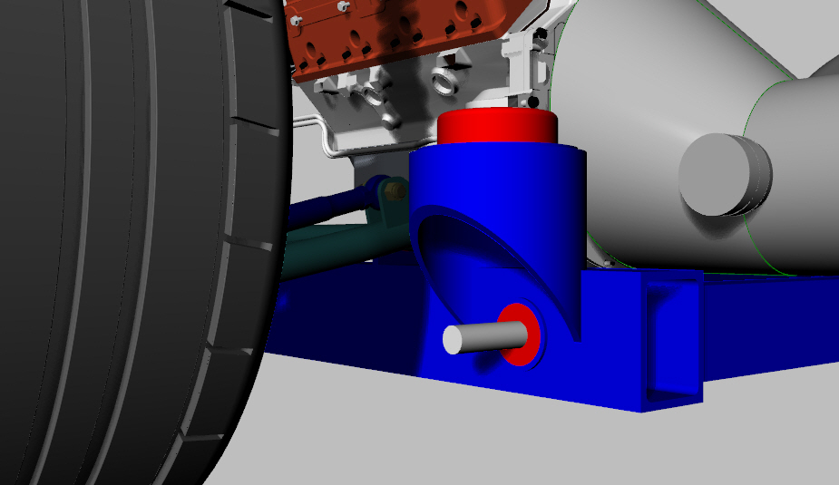
It would seem the only logical path for the sway bar is to pass through the engine cradle rails. As can be seen above, I inserted a tube through each of the two cradle rails which would allow the cradle to pass through. The plan is to fit these two tubes with poly bushings, similar to the control arm bushings and these would support the sway bar while allowing it to flex freely.
|
|
|
|
Along with a custom sway bar rod, there will be sway bar arms and linkages that connect to the mounting plates on the control arms.