the 3" chassis stretch
June 16 2012
When building a Ferrari 355 style car on a stock Fiero chassis, one of the first decisions to be made is whether or not to stretch the chassis to match the wheelbase of the actual 355. The stock Fiero chassis has a wheelbase of 93.4" where the actual 355 has a wheelbase of 96.4". That means a 3" chassis stretch is required if you wish to retain the general proportions of the 355. It is generally accepted that the easiest way to stretch the Fiero chassis is to cut the upper (2) and lower (2) frame rails just behind the firewall in the engine compartment. The alternatives to this operation is to cut the passenger cabin transversely which requires much more work to weld the two halves back together with a 3" spacer or leave the chassis at stock length and move only the rear strut towers rearward to obtain the desired extended wheelbase. The difficulty in this lies with the fact that this moves the strut towers into the trunk space where the upper frame rails begin dropping down meaning that the rear wheels will no longer clear the rear structure of the chassis.
For this project, I have chosen to cut the frame rails approximately 6" behind the firewall. At this location, the frame rails are running straight and level and it provides ample structure to weld the 3" spacers to.
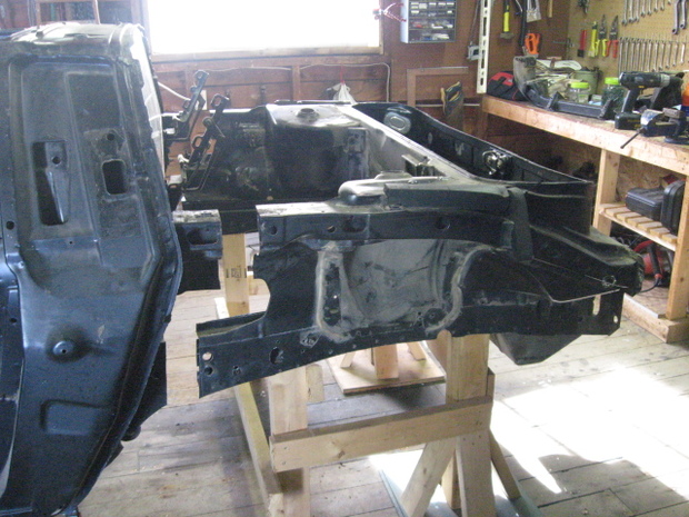
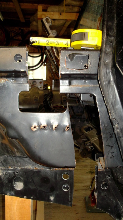
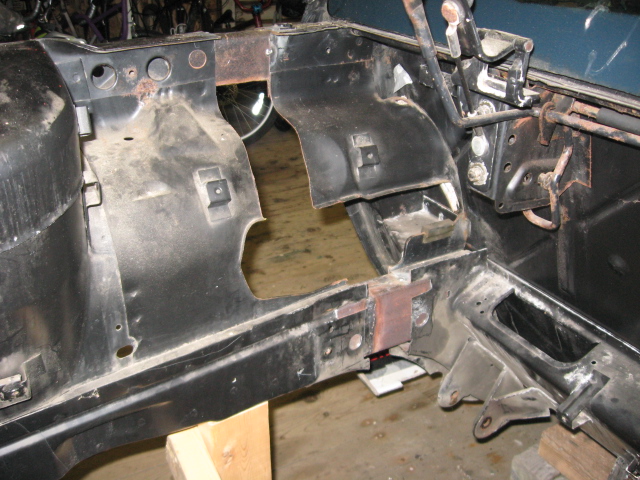
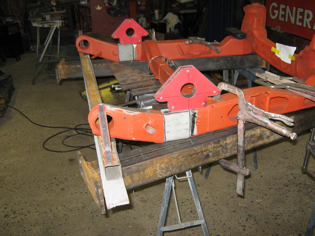
Here is my stock chassis cut and the back section moved rearward 3". Its important to support both halves of the chassis adequately during this operation so that the alignment can be retained and confirmed during the process to reconnect the chassis halves back together.
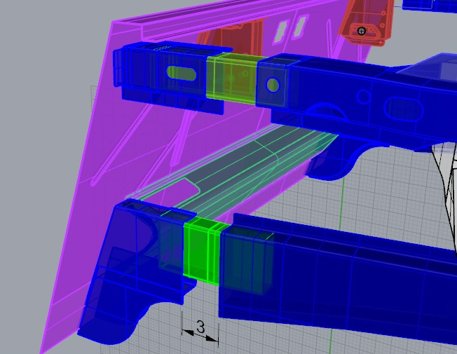
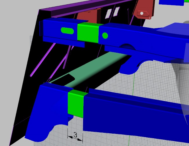
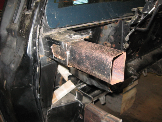
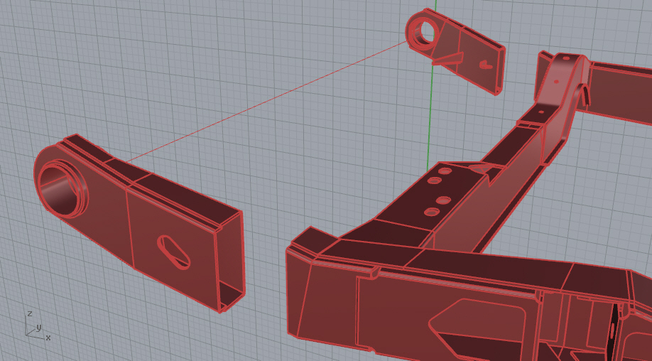
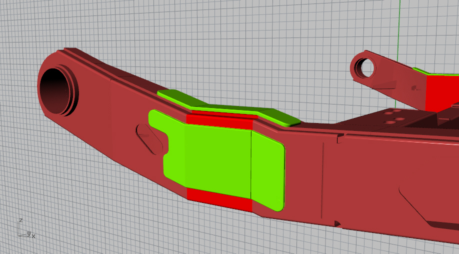
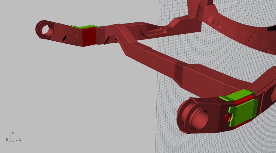
Once the chassis is cut , it is necessary to fabricate joining structure to span the 3" gap. The upper frame rail spacer was fabricated using 1/16" plate and bent into a non uniform square section to replicate the cross sectional shape of the stock frame rail. The pieces were made 8" long which allowed them to be slid inside the existing frame rail ends by 2 1/2" producing the 3" span. Prior to final fitting, a series of holes were made in the frame rails to allow additional plug welds to be used to help hold the structure together. Here is a 3D model of the drivers side upper and lower frame rails showing the 3" stretch with the 8" spacers fitted inside.
August 12 2012
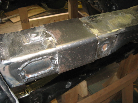
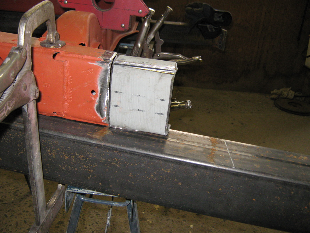
Here are the actual parts fitted in the upper and lower frame rails.
Here are the actual parts fitted in the upper and lower frame rails.
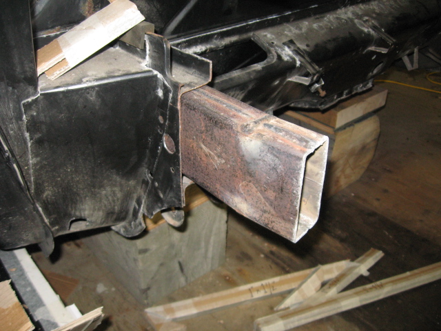
The lower frame rail sections were fabricated and fitted in a similar manner. They were fabricated from 8" long sections of 4" x 2" x 1/8" HSS that were split and then welded back together to form the necessary section 4" x 1 3/4" x 1/8". You will notice that the lower filler piece has a slight kink to align with the jog in the actual frame rail. Like the upper frame rails, the sections for the lower frame rails were inserted 2 1/2" into each end of the stock frame rails.
August 21 2012
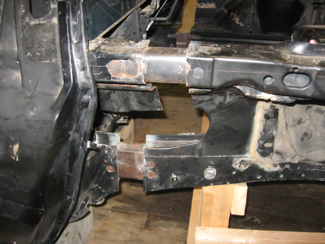
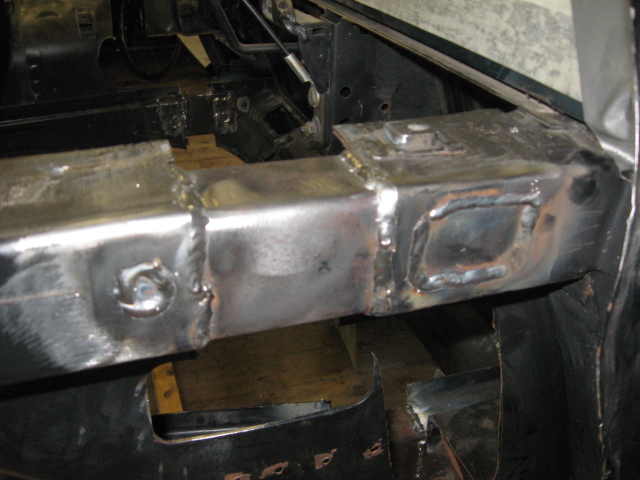
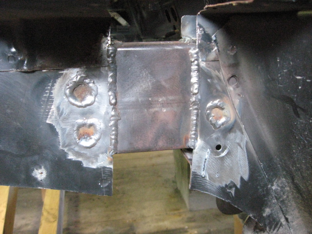
With the chassis halves put back together with the splicing pieces securely inserted in the frame rails, the stretch length is confirmed and alignment of the front and rear halves of the chassis is double checked to ensure the everything is square and true. Then the welding is completed, making an effort to prevent heat building up in any one area and minimizing chassis distortion.
With the chassis halves put back together with the splicing pieces securely inserted in the frame rails, the stretch length is confirmed and alignment of the front and rear halves of the chassis is double checked to ensure the everything is square and true. Then the welding is completed, making an effort to prevent heat building up in any one area and minimizing chassis distortion.
Once the welding of the structure was complete, I decided to cap the new extensions with 1/16" plate that was formed to cover the extensions and once welded in place, ground smooth to hide the extension work. Once sanded and painted, the extension will be hidden from all but the experienced eyes.
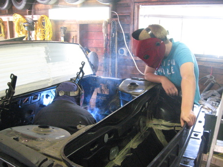
Always ensure you have adequate supervision when welding in a shop with a wooden floor :)
Oct 1 2012
Once you have completed the 3" stretch of the chassis, its going to be necessary to make an equivalent 3" stretch of the engine cradle. This will ensure that the suspension mounting points stay aligned with the new location of the strut towers.
Like the chassis stretch, there are several ways to accomplish this task, depending on where you cut the engine cradle. I chose a location in front of the forward cross member where the cross section of the cradle frames is straight and of uniform cross section. This makes alignment of the parts simpler and fabrication of the spacers much easier.
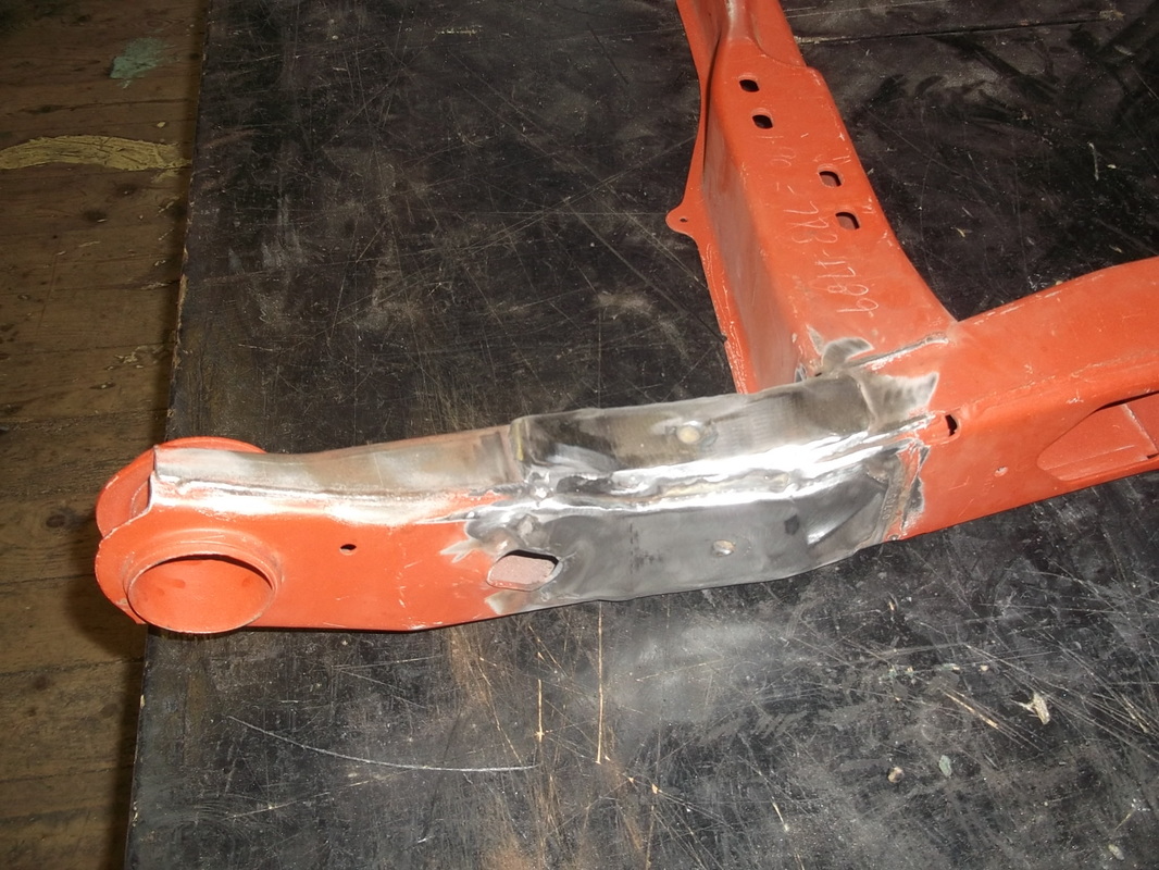
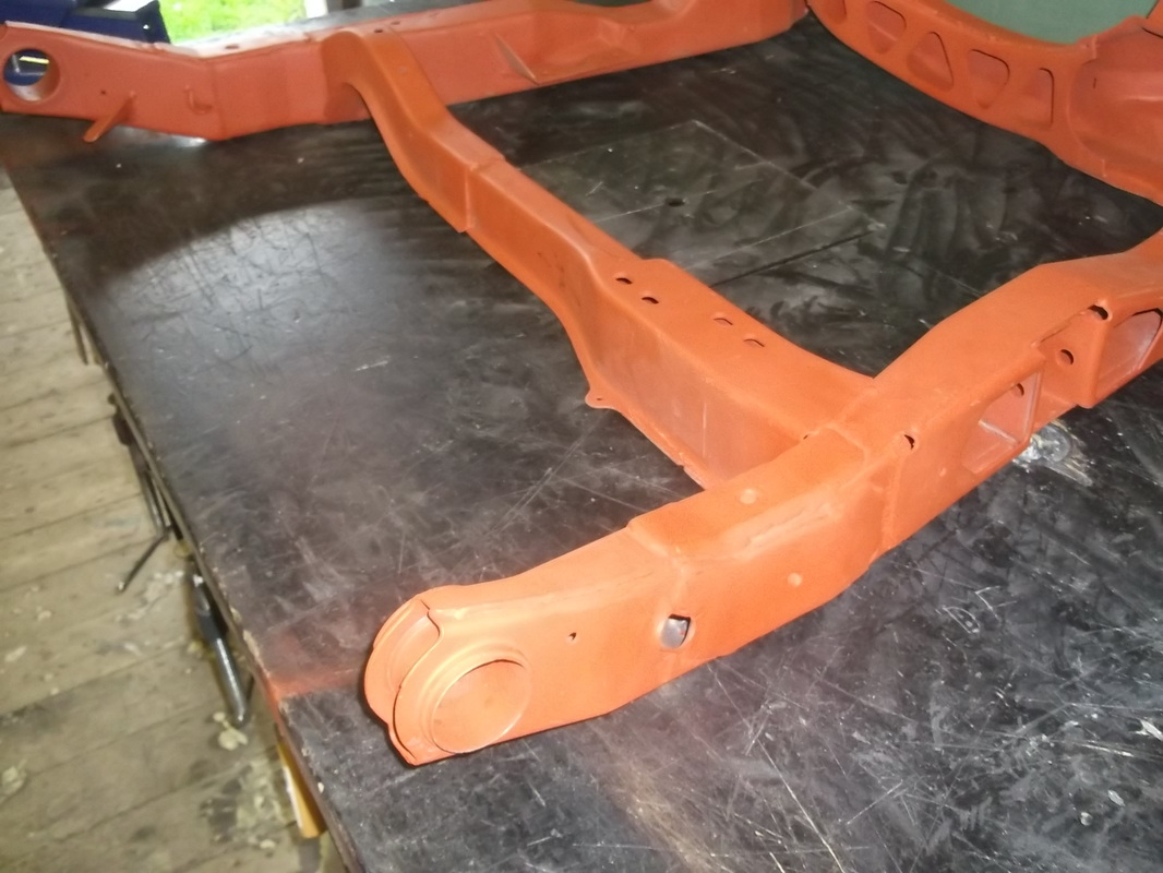
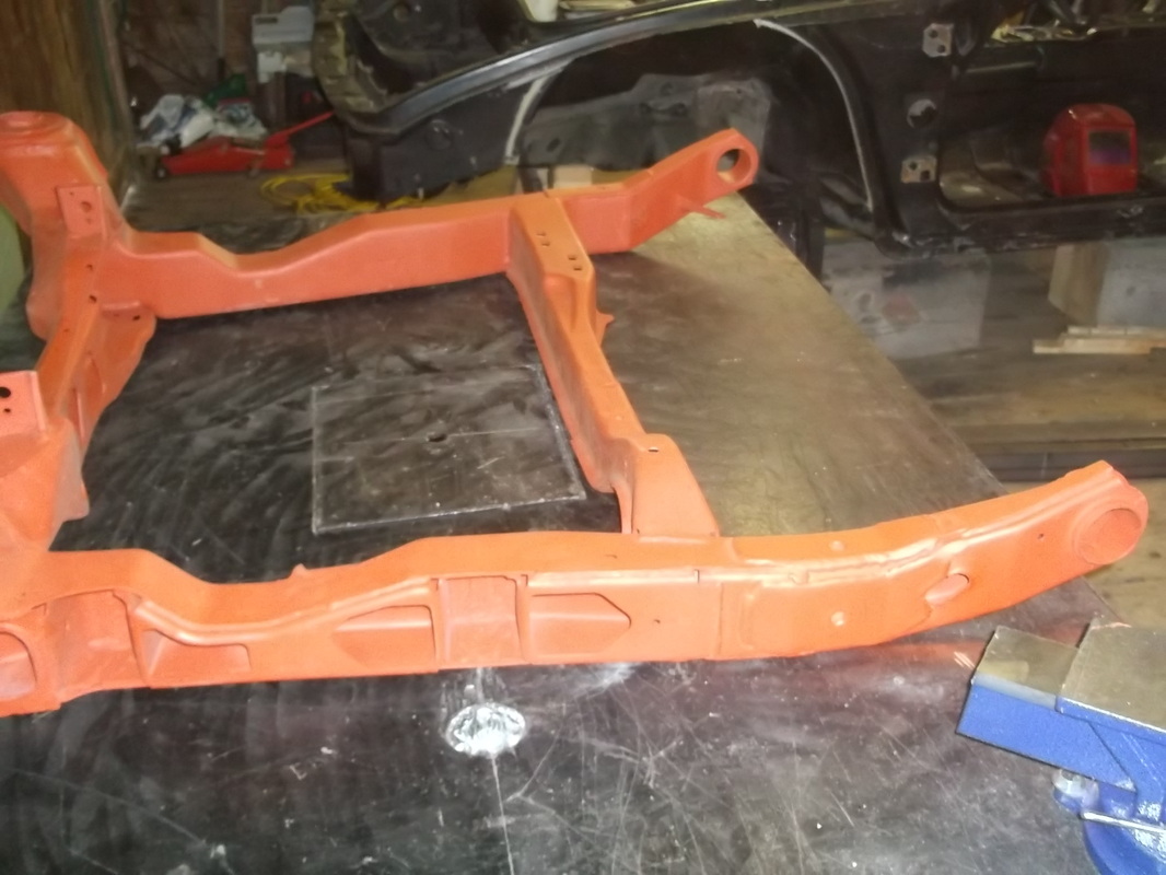
Here are a couple images of the cradle cut and stretched 3". For the 3" spacer I used a 4" x 2" x 1/8" HSS split in two and then reassembled with the flanges overlapped to replicate how the OEM cradle has been fabricated from multiple stamped parts.
Here are a series of pictures showing the cradle cut, the extensions inserted and the entire assembly reconnected, ready for welding. I can't stress enough the importance of keeping everything flat and square during this entire operation. If you don't and the cradle gets twisted or warped, the car will have significant problems driving a straight line down the road later.
Oct 20 2012
When the cradle was assembled and welding of the 3" spacer was complete, I added two stiffening plates to each side that spanned the 3" stretch and helped add additional strength. You'll notice that unlike the frame stretch above, the 3" spacers for the cradle stretch only butt to the cradle ends as opposed to fitting inside the frames rails like the above chassis stretch. Adding the stiffening plates ( fish plates in the marine world) isn't necessarily required but it gives me piece of mind.
When the cradle was assembled and welding of the 3" spacer was complete, I added two stiffening plates to each side that spanned the 3" stretch and helped add additional strength. You'll notice that unlike the frame stretch above, the 3" spacers for the cradle stretch only butt to the cradle ends as opposed to fitting inside the frames rails like the above chassis stretch. Adding the stiffening plates ( fish plates in the marine world) isn't necessarily required but it gives me piece of mind.

